background image

Installation manual antennas 

38

Modifications, misprints and errors excepted

English

5. Installation

The MiRa and WiRa antennas are relatively insensitive to the type of attachment and the materials surrounding 

the antennas. Nevertheless few conductive objects in the vicinity of the antenna should be presented. In addition, 

other objects, such as containers with liquids in the vicinity of the antenna affect their functionality. In such cases, 

a reassessment of the antenna in the particular installation conditions is necessary. The LoRa antennas are very 

robust and suitable for installation in metallic environment.

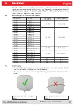
•  The cable should be laid vertical (see Figure 13) away from the antenna and should be laid direct. The cable 

length is to be selected as short as possible to minimise cable losses.

•  Cable loops around the antenna, as shown in Figure 12, or laying the cable in front of the antenna are to be 

avoided.

X

5.2. 

Cable laying

5.1. 

Connecting kit for antennas and readers

Order number

Type reader

Order number

Connecting Kit

Type Conneting Kit

52010093

RRU4-RS4-E6

52010125

CK-RRU RS4

52010096

RRU4-RS4-U6

52010099

ARU4-RS4-E6

52010102

ARU4-RS4-U6

52010094

RRU4-ETG-E6

52010126

CK-RRU ETG

52010095

RRU4-ETL-E6

52010097

RRU4-ETG-U6

52010098

RRU4-ETL-U6

52010100

ARU4-ETG-E6

52010101

ARU4-ETL-E6

52010103

ARU4-ETG-U6

52010104

ARU4-ETL-U6

52010225

ARU4-ELK-E6

52010226

ARU4-ELK-U6

52010135

M-ARU RS232

52010189

CK-M-ARU RS

52010136

M-ARU RS232 FCC

52010180

M-ARU-ELC-E6

52010209

CK-M-ARU PoE

52010181

M-ARU-ELC-U6

52010198

M-ARU-ETH-E4

52010199

M-ARU-ETH-U4

52010190

ERU4-ETG-E4

kein

kein

52010191

ERU4-ETG-U4

kein

kein

52010200

RDR-ETH-E4

kein

kein

Figure 24: Do not lay cable around the

antenna! 

Figure 23: Do not lay cable in front of the

antenna

5. Installation

Summary of Contents for 52010078

Page 1: ...2 This document is valid for all Kathrein RFID antennas and describes the construction and the installation of the antennas Low Range Antennas Mid Range Antennas SMSH Antennas modul SMSH KRAI Antennas...

Page 2: ...hout protective cover 52010260 Type Order number WiRa 70 ETSI Wide Range antenna ETSI 865 870 MHz 70 circular 52010078 WiRa 70 FCC Wide Range antenna FCC 902 928 MHz 70 circular 52010079 WiRa 70 KRAI...

Page 3: ...he information contained in this manual is intended for the support of the development process and as development guidance for the customer In addition this manual offers supporting information about...

Page 4: ...actor EIFF shows the field isoltaion from far field to near field in realation to the isotropic monopole EIRP Equivalent Isotropically Radiated Power EN Europ ische Norm European standard ERP Effectiv...

Page 5: ...nas 10 3 3 SMSH antennas module 10 3 4 Wide range Antennas 11 3 5 KRAI Antennas 13 3 6 Antenna type according to read range and transponder shape 12 3 7 Maximum reading range 13 4 Technische daten 14...

Page 6: ...allation manual antennas 6 Modifications misprints and errors excepted English List of contents 5 4 Assignment Wall mast clamp to antennas and readerse 29 5 5 Installation drawings 30 6 Contact addres...

Page 7: ...which was valid at the time of purchase We accept no liability for unsuitable manual or automatic adjustments made to the unit s parameters and inappropriate use of the unit Repairs may only be undert...

Page 8: ...sly in any combination with Kathrein RFID reader This modularity is only possible with Kathrein RFID readers and antennas 0 to 10 cm with Low Range antenna 20 cm to 2 m with Mid Range antenna 1 m to 1...

Page 9: ...y GPIOs and RS232 interface M12 open length 1 5 m 52010209 CK M ARU PoE Combination cable for power supply and PoE interface M12 RJ 45 length 1 5 m 52010238 R CC 10 ETH Ethernet Connecting cable RRU4...

Page 10: ...oor 52010262 MK WM 100 100 Indoor Wall mount mast mounting set for WiRa 70 antennas and RRU ARU Reader Indoor Mounting Accessories Protective Covers Order number Type Product type 52010179 R RPA 115 2...

Page 11: ...56 x 126 mm MiRa also offers increased selectivity at lower reading distances compared with conventional antennas This antenna design is therefore also suitable for use in the so called transition are...

Page 12: ...on to the an tennas available on the market For the so called axial ratio which is used as a characteristic value for circular polarization the two new models achieve typical values of 1 dB If specifi...

Page 13: ...tremely thin design the antenna module can be integrated into different applications universal The antenna is equipped with an intelligent bypass circuit that allows for cascading up to 8 SMSH modules...

Page 14: ...na On the connector side of the antenna the position RIGHT is defined These CSB antennas are used to detect the movement of the transponder This information will be transferred in combination with the...

Page 15: ...sponders at distances up to 10cm and the dipole type transponders at distances up to 100cm MiRa can read loop shaped transponders up to 30 cm hybrid form transponders up to 100 cm and dipole form tran...

Page 16: ...certain applications As a result of the consistent continuation of the platform strategy for antenna and reader all product and interface variants already introduced are available in nu merous combin...

Page 17: ...0 5 Connection TNC socket TNC socket TNC socket Protection class IP 67 IP 67 IP 67 Weight g 110 110 110 Dimensions W x H x D mm 79 5 x 90 x 31 79 5 x 90 x 31 79 5 x 90 x 31 Packing dimensions approx m...

Page 18: ...ata Loop shaped near field tags Hybrid Dipole form far field tags Tag types Ultra Low range antenna Low range antenna LoRa antennas are only suitable for loop shaped tags There is no defined reading z...

Page 19: ...ratio dB 8 depending upon installation situation Max input power FCC15 247 ETSI EN 302 208 W 1 0 Far field half power beam width 100 half power beam width Connection TNC socket Protection class IP 67...

Page 20: ...nts and errors excepted English 4 Technical data The antenna directivity shows the propagation characteristics of the EM field of the antenna The half power beam width and the front to your ratio can...

Page 21: ...ion situation 10 depending upon installation situation Max radiated power ETSI EN 302 208 W 1 0 ERP Max input power FCC 15 247 W 1 0 Far field half power beam width 100 half power beam width 100 half...

Page 22: ...prints and errors excepted English 4 Technical data The antenna directivity shows the propagation characteristics of the EM field of the antenna The half power beam width and the front to your ratio c...

Page 23: ...Front to back ratio circular dB 20 Max radiated power ETSI EN 302 208 W 33 33 Max input power FCC 15 247 W 30 at Antenna port Far field half power beam width 60 60 Connection input SMA socket output...

Page 24: ...3 ETSI EN 302 208 33 ETSI EN 302 208 Max input power FCC 15 247 W 30 an Antennen Buchse Far field half power beam width 60 60 Connection input SMA socket output SMA socket Protection class Indoor Weig...

Page 25: ...Installation manual antennas 25 Modifications misprints and errors excepted English 4 Technical data Figure 15 Antenna diagram SMSH...

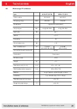
Page 26: ...1 VSWR 1 2 1 Impedance 50 Front to back ratio dB 18 Max radiated power W 2 0 ERP ETSI EN 302 208 4 0 EIRP FCC 15 247 Far field half power beam width 69 69 Connection TNC socket Protection class IP 65...

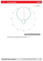
Page 27: ...prints and errors excepted English The antenna points to the propagation characteristics of the EM field of the antenna It would therefore appear the opening angle and the front back ratio 4 Technical...

Page 28: ...247 Far field half power beam width 69 69 Connection TNC socket Protection class IP 65 Weight kg 1 7 Dimensions W x H x D mm 271 x 271 x 45 Packing dimensions approx mm 300 x 300 x 150 Material Antenn...

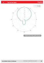
Page 29: ...Installation manual antennas 29 Modifications misprints and errors excepted English 4 Technical data Figure 17 Antenna diagram WiRa 70 KRAI ETSI FCC...

Page 30: ...tio dB 18 25 Max radiated power W 33 ERP ETSI EN 302 208 36 EIRP FCC 15 247 max input power W 30 at antenna port Far field half power beam width 42 42 40 40 Connection N female Protection class IP 65...

Page 31: ...Installation manual antennas 31 Modifications misprints and errors excepted English 4 Technical data Figure 18 Antenna diagram WiRa 40 linear ETSI FCC...

Page 32: ...EN 302 208 W 33 ERP ETSI EN 302 208 30 at antenna port FCC 15 247 Far field half power beam width 30 vertical 70 horizontal Connection N female Protection class IP 65 Weight kg 3 7 Dimensions W x H x...

Page 33: ...Installation manual antennas 33 Modifications misprints and errors excepted English 4 Technical data Figure 19 antenna diagram WiRa 40 linear ETSI FCC...

Page 34: ...d power FCC 15 247 W 1 W 30 dBm conducted Far field half power beam width 30 69 Connection N socket Protection class IP 65 Weight kg 3 7 Dimensions W x H x D mm 557 x 262 x 59 Packing dimensions appro...

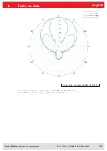
Page 35: ...prints and errors excepted English 4 Technical data The antenna points to the propagation characteristics of the EM field of the antenna It would therefore appear the opening angle and the front back...

Page 36: ...W 30 Far field half power beam width 35 vertical 80 horizontal Connection N socket Protection class IP 65 Weight kg 3 7 Dimensions W x H x D mm 557 x 262 x 59 Packing dimensions approx mm 762 x 356 x...

Page 37: ...rints and errors excepted English 4 Technical data Figure 21 Read range vertical cut WiRa 30 KRAI ETSI antenna Figure 22 Directions of the WiRa 30 CSB KRAI ETSI antenna Please note that the Beam R is...

Page 38: ...able losses Cable loops around the antenna as shown in Figure 12 or laying the cable in front of the antenna are to be avoided X 5 2 Cable laying 5 1 Connecting kit for antennas and readers Order numb...

Page 39: ...ised sheet stell Screw hose clip stainless steel Items supplied Wall plate mounting plate mast clamp hose clip 8 screws M5x10 8 shims 4 screws M6 10 5 3 Wall mast clamp Selecting the installation loca...

Page 40: ...h variours pre drilled holes suitable for Wide range antennas ect Order number 52010005 Max load bearing capacity kg Adjustment range 90 Weight unpacked kg 1 5 Dimension of the packing mm 200 x 150 x...

Page 41: ...61 Max load bearing capacity kg 6 0 Adjustment range 30 Azimuth 45 Elevation Weight unpacked kg ca 0 6 Dimension of the packing mm 150 x 120 x 80 Material Stainless steel and galvanized steel fastener...

Page 42: ...iRa FCC X 52010172 S MiRa ETSI FCC X 52010193 WiRa 70 KRAI ETSI X X X 52010194 WiRa 70 KRAI FCC X X X 52010227 WiRa 30 CSB KRAI ETSI X 52010228 WiRa 30 CSB KRAI FCC X 52010248 WiRa 30 linear ETIS X 52...

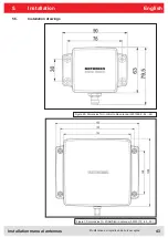
Page 43: ...ntennas 43 Modifications misprints and errors excepted English 5 5 Installation drawings Figure 29 Dimensios for U LoRa LoRa antenna 52010092 84 85 Figure 30 dimensios for MiRa S Mira antenna 52010172...

Page 44: ...Installation manual antennas 44 Modifications misprints and errors excepted English Figure 31 Dimensions for WiRa 70 antenna 52010078 79 5 Installation...

Page 45: ...Installation manual antennas 45 Modifications misprints and errors excepted English 5 Installation Bild 32 Abmessungen f r WiRa 40 52010251 252...

Page 46: ...Installation manual antennas 46 Modifications misprints and errors excepted English Figure 33 Dimensions for WiRa 30 antenna 52010086 87 5 Installation...

Page 47: ...errors excepted English Figure 35 Dimensions for WiRa 30 CSB KRAI antenna 52010227 228 Figure 34 Note left right installation WiRa 30 CSB KRAI antenna 52010227 228 5 Installation Please note that the...

Page 48: ...antennas 48 Modifications misprints and errors excepted English Address Contact Kathrein RFID E Mail rfid sales kathrein rfid de Kronstaudener Weg 1 Internet www kathrein rfid de D 83071 Stephanskirch...

Reviews: