background image


d.7 Room probe 

d.8 Sparking plug 

d.9 Thermocouple 


E. ORDINARY CLEANING AND MAINTENANCE  

e.1 Cleaning and maintenance by the customer  

e.2 Periodic maintenance by the Assistance Center 


F. ALARMS DISPLAYING  

f.1  Fumes temperature probe alarm 

f.2  Unsuccessful lighting alarm 

f.3  Switching-off while working alarm 

f.4  Power failure alarm 

f.5  Room thermocouple alarm 


G. SOLUTIONS TO POSSIBLE PROBLEMS 

Summary of Contents for Alice

Page 1: ...PELLET STOVE ALICE OPERATING AND MAINTENANCE HANDBOOK ...

Page 2: ...ay know and use the product at its best as well as ordinarily upkeep it Our authorized technical service remains at Your complete disposal for any necessity Best regards Karmek One S R L PLEASE NOTE Karmek One reserves itself to carry out unsubstantial changes to the stove s components which may not be reported in the present handbook those being of small entity Occasional appearance changes from ...

Page 3: ... Installing the combustion air inlet pipe b 6 Connecting to the power supply C OPERATING INSTRUCTIONS c 1 Initial warnings c 2 Introduction c 3 Display c 4 Lighting the stove for the first time c 5 Activating the stove c 6 Room temperature setting c 7 Switching off the stove c 8 The remote control c 9 Managing the automatic lighting chronothermostat D FUNCTIONS OF THE MECHANICAL AND ELECTRIC COMPO...

Page 4: ...aning and maintenance by the customer e 2 Periodic maintenance by the Assistance Center F ALARMS DISPLAYING f 1 Fumes temperature probe alarm f 2 Unsuccessful lighting alarm f 3 Switching off while working alarm f 4 Power failure alarm f 5 Room thermocouple alarm G SOLUTIONS TO POSSIBLE PROBLEMS ...

Page 5: ...raught before and after the combustion work of the stove While seasonally using the stove in case of bad draught of unfavorable weather conditions temperature lesser than 0 C verify if the flue i s perfectly cohibented and not obstructed so to avoid its freezing and the danger of a reflux In case of fire inside the flue immediately switch the stove off The stove consumes as much air as it is neces...

Page 6: ...uch the glass when the stove reaches its temperature be cautious before touching the stove Avoid letting children close to the stove on their own when it is on because each hot surface can provoke severe burns Do not perform interventions on the stove apart from those expected for a regular functioning or suggested in this handbook in order to solve slight problems In any case always unplug the st...

Page 7: ...ustable feet YES Dimensions mm 867x1077x273 Weight 100Kg Fuel pellet Ø6mm Fumes joint Ø80mm Air inlet Ø30mm Minimum safety distance from inflammable materials 200mm a 3 Accessory equipment The stove is equipped with a remote control a supply cable adjustable feet a handbook a 4 Identity plate The identity plate is positioned on the back of the stove and it reports the following data commercial bra...

Page 8: ...8 ALICE 1 Rear fumes outlet 2 Side fumes outlet 3 Upper fumes outlet ...

Page 9: ...e of various wooden materials pellets are compliant to DIN 51731 regulations The following list summarizes the main characteristics of recommended pellets Diameter 6 6 5mm Maximum length 20 25mm Caloric output Approx 4 600 Kcal Kg Humidity 12 Ash content 1 5 Specific weight and density Kg dm 1 0 1 4 The stove is built to burn not resinous preferably beech wood pellets therefore using pellets whose...

Page 10: ...flue Extraction fans can cause problems when used in the same room or space of the device b 2 Moving and transporting Make sure that the devised used for lifting and transporting the stove support its weight which is reported on the identity plate on the back of the stove The lifting of the stove is normally performed with an elevation trolley by inserting the pitchforks in the proper slots of the...

Page 11: ...ntally proceed vertically until you reach the roof with a cohibented flue equipped with an anti wind chimneystack All the joints must be sealed FIG 2 INSTALLATION WITH AN EXISTING FLUE Flue gas outlet Ø 80 Reach the existing flue horizontally making sure that it presents a minimum section of 200cm and an easy to inspect base for its annual cleaning All the joints must be sealed IMPORTANT We recomm...

Page 12: ...12 Combustion air is drawn from the inside Combustion air is drawn from the inside INSTALLATION WITHOUT A MASONRY FLUE INSTALLATION WITH AN EXISTING FLUE Masonry flue Steel piping ...

Page 13: ...d flue b 6 Connecting to the power supply Verify if the electrical system and the mains outlets present the capacity to support the maximum absorption of the stove which is reported on the plate Make sure the system is provided with a norm compliant earthing and differential switch The stove must be connected to a norm compliant 230v 50Hz mains outlet Avoid using adapters multiple sockets or exten...

Page 14: ...14 ELECTRICAL SCHEME ...

Page 15: ...n automatic management of the temperature of the lighting and the switching off with the possibility of a multiple days programming The automatic loading and the consistent capacity of the tank allow the pellet stove to perform automatically for a longer time and they permit a better management of the device If the stove reaches the set values and the temperature keeps constant for a certain amoun...

Page 16: ...3 Display In the following scheme we report the various functions of the display IMPORTANT If the temperature is not set within a few seconds the display will automatically return to the previous screenshot ...

Page 17: ...gh the stove is brought to the control mode which will make the message FIRE ON appear on the display In the while the pellet supply is increased to raise the temperature even higher with a defined gradient approximately 3 C per minute When the pellets inside the grate are completely burned the stove proceeds in its normal functioning To load the pellets remove the lid from the upper part of the s...

Page 18: ...ient to push the key n 6 for approximately 2 seconds This operation will immediately restart the working phase ON the complete lighting phase can be spared if the temperature of the fumes is higher than 50 60 c 8 The remote control The provided remote control permits to perform the following functions to light and to switch off the stove point the remote control while pushing the upper keys marked...

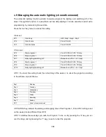
Page 19: ...y lighting switching off Between on off for 1 to 7 days UT8 Start program 1 From 00 00 to 23 50 10 step UT9 Stop program 1 From 00 00 to 23 50 10 step UT10 Daily lighting switching off Between on off for 1 to 7 days UT01 You need this setting to set the current day of the week or to unset the program according to the scheme reported below Day1 Monday Day 2 Tuesday Day 3 Wednesday Day 4 Thursday Da...

Page 20: ...ing time of the Program 2 if the UT01 setting is set on the weekly mode different from OFF UT10 it modifies the weekdays you wish the Program 2 to be on By pressing the 2 key you run over the days and by pressing the 1 key you set or unset the program ...

Page 21: ...ber This operation permits a perfect combustion and a better thermic efficiency d 3 Tangential fan The tangential fan intakes the room air and returns it hot by pushing it through the exchanger tubes d 4 Electronic card The electronic card guarantees the correct functioning and the maximum safety of the stove in the management of all of its functions d 5 General switch This electronic component of...

Page 22: ...he temperature of the room where the stove is located d 8 Sparking plug The sparking plug permits the primer of the flame inside the grade The lighting of the pellets occurs because of the overheating of the plug and the heating of the air inside the combustion chamber d 9 Thermocouple The thermocouple junction is positioned on the side of the tank and it operates by unsetting the functioning of t...

Page 23: ...pipe of the stove Remove the furnace s internal covering accurately clean and remove the incrustations inside the crucible and its space Clean the fans and check the mechanism of the plays and of the fixings Clean inspect and remove the incrustations of the lighting resistance and its space Clean the display and the remote control Inspect the electrical cables the connections and the supply cable ...

Page 24: ...ck for the wires to be properly connected or substitute the fumes probe if necessary f 2 Unsuccessful lighting alarm It occurs when the lighting phase is unsuccessful or in case the stove does not reach the lighting temperature at a gradient of 3 C per minute The s tove will automatically activate the switching off procedure f 3 Switching off while working alarm It occurs if the flame runs out or ...

Page 25: ...lation of too many pellets in the grate Clean the grate The stove does not light automatically The resistance does not reach its temperature Damage or exhausted resistance The pellets do not descend Check the electric cables and fuses Call the assistance center to substitute the resistance if damaged Substitute the resistance IMPORTANT unplug the stove before checking if the pellets are embedded i...

Page 26: ... the outlet flow Insufficient intake in the grate Recent change in the kind of pellets used See the paragraph about the installation of the stove Check if the flue is clean Check the quality of the pellets Contact the authorized assistance center Check the anti wind terminal and or install it if necessary Check if the grate is correctly positioned and if it is clean check is the air intake pipe is...

Page 27: ...27 ...

Page 28: ...Conegliano TV phone 0438 1883101 fax 0438 1883103 e mail info karmek it GUARANTEE CONDITIONS AT THE END OF EACH SEASON IT IS OBLIGATORY TO HAVE THE AUTHORIZED ASSISTANCE CENTER PERFORM A GENERAL CLEANING OF THE STOVE OTHERWISE THE GUARANTEE WILL EXPIRE ...

Reviews: