background image

Further informations on: 

www.karmaitaliana.it

7

6

AUTO MODE

Through the display (7) and its keys  (A.B,C,D) select one of the two auto 

modes (Pr00 or Pr 01 / Pr 018). You can then adjust the effect speed 

through the values S001 - S255 and, if you like, the flashing (FL 01- FL 04)

SOUND ACTIVATED MODE

Through the display (7) and its keys  (A.B,C,D) select one of the three 

“sound” programs (Sd00 or Sd01/Sd16).  The device will light on according 

to the music rhythm, perceived thanks to the small microphone inside it (11)

MASTER SLAVE /MODE

In this mode you can connect more than one device of the same model 

so that they will be synchronized.  To do that, the first unit will operate in 

standard way, while all the others (slaves) will be connected to the first 

(master) in daisy chain, using the DMX connectors (4) and XLR cables.

 All the units connected to the master must be set in SLAVE mode through 

the specific menu.

 In this way the slave units will run exactly the same programs as the 

master unit.

DMX MODE

In a DMX 512 linking there are 512 channels available.

Each DMX fixture uses one or more channels to manage its functions. The 

user must assign a starting address to each DMX fixture.  This address 

will indicate the first channel used on the controller. You have to plan the 

starting address choice in order to avoid channels’ overlapping. Otherwise 

the fixture wouldn’t work correctly.

 Example: If you need to connect 3 DMX fixtures, each with 10 channels, 

the first unit is to be set on address 1, the second unit on address 11 

and the third one on address 21.  Anyway you can set the same starting 

address on more devices if you wish them to operate in synchrony.   DMX 

devices are conceived to receive datas through a serial Daisy Chain 

connection.  With this kind of linking the datas output of a fixture is 

connected to the data input of the following one. The order of linking of the 

devices is not important and it doesn’t affect on how the controller manages 

each of them.  We suggest to put them in the easiest and most direct 

sequence for cable connection.  The cable length should not be more than 

100mts to avoid interferences with other signals or electric devices. When 

you arrange the connections make sure that the fixtures and the cables use 

Instructions

Summary of Contents for DJ LED233

Page 1: ...w w w k a r m a i t a l i a n a i t Instruction manual E DJ LED233 Disco light effect...

Page 2: ...ake sure the voltage of the power source used for the product is correct This product is not suitable for outdoor use To avoid the risk of fire or short circuits never expose the fixture to rain or mo...

Page 3: ...perature higher than 40C In the event of a serious operating problem stop using the product immediately Never try to repair the product but contact the authorized technical assistance center Repairs c...

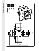
Page 4: ...4 Pictures and plugs 3 A 7 B 12 7 6 5 9 4 8 11 10 C D 2 1...

Page 5: ...lation connect the input and output cables to the DMX IN OUT sockets 4 5 Connect the power cable to the fixture s socket 8 and then to the 230V mains If you want to connect other light effects in dais...

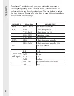
Page 6: ...1 16 uEr Software version Only if used with remote controller rEd Red GrEE Green bLUE Blu AnbE Amber St00 St04 Strobo speed in color mode OFF OFF The display 7 and its keys will help you in setting t...

Page 7: ...nels available Each DMX fixture uses one or more channels to manage its functions The user must assign a starting address to each DMX fixture This address will indicate the first channel used on the c...

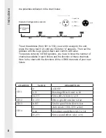
Page 8: ...ate correctly in DMX systems you have to know the number of channels available in each fixture and the function of these channels Here is the chart with the functions of the 4 DMX channels of your new...

Page 9: ...hing speed DMX It enables and disables DMX mode Press it for about 2 seconds to enable it Manual Once pressed the key it will be possible to choose manually the color of the light beams To do that you...

Page 10: ...10 Notes...

Page 11: ...components come to an authorized disposal center for collection of waste electronic and electrical or returning it to the dealer when buying new equipment of equivalent type at a rate of one to one Ap...

Page 12: ...replacement External components batteries knobs switches and any removable or subject to wear and tear parts are excluded from warranty Shipment for the return of faulty items is at expense and risk o...

Page 13: ...ZIA GUARANTEE CERTIFICATE CERTIFICATO DI GARANZIA GUARANTEE CERTIFICATE MODULO DI REGISTRAZIONE REGISTRATION MODULE MODULO DI REGISTRAZIONE REGISTRATION MODULE COPIA DA INVIARE A COPIA DA CONSERVARE S...

Page 14: ...ICE NUMBER N SCONTRINO O FATTURA RECEIPT INVOICE NUMBER TIMBRO E FIRMA DEL RIVENDITORE DEALER S STAMP AND SIGNATURE TIMBRO E FIRMA DEL RIVENDITORE DEALER S STAMP AND SIGNATURE ACQUISTATO DA PURCHASED...

Page 15: ...IR remote controller Included Led s life around 50 000 hours Consumption 72W Color Black Operation modes Sound auto DMX master slave Remote DMX channels 4 Channels Bracket Adjustable Operation tempera...

Page 16: ...ver 16 1 Via Gozzano 38 bis 21052 Busto Arsizio VA Italy Telefono 39 0331 628 244 Fax 39 0331 622 470 www karmaitaliana it made in China...

Reviews: