Kärcher K 6.200, Service Manual
The Kärcher K 6.200 is a powerful and efficient pressure washer that ensures optimal cleaning results. For easy maintenance and troubleshooting, you can conveniently access the Service Manual on our website. Discover how to keep your product in top condition and download the manual for free at manualshive.com.
Share
Download


Reviews:
No comments
Related manuals for K 6.200
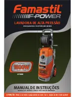
LV1800
Brand: Famastil Pages: 40

UWM-9106
Brand: UNITED Pages: 80

WDI12C1
Brand: Smeg Pages: 30

SPWD2200
Brand: Summit Pages: 15

WIXL 105
Brand: Indesit Pages: 72

8640FE
Brand: Big boss Pages: 20

HV5L 125 A
Brand: Hotpoint Pages: 16

WW80H5290E Series
Brand: Samsung Pages: 88

WW75K5 Series
Brand: Samsung Pages: 112

WW9-J4 Series
Brand: Samsung Pages: 120

WW8 J3 Series
Brand: Samsung Pages: 336

WW9*K7 Series
Brand: Samsung Pages: 960

WW80J3 Series
Brand: Samsung Pages: 52

XQB70-10
Brand: Haier Pages: 20

WM50
Brand: Asco Pages: 11
atf7000es
Brand: Frigidaire Pages: 9

ATF705X
Brand: Frigidaire Pages: 18

ATF7000EE0
Brand: Frigidaire Pages: 6


