background image

– 1

Please read and comply with 
these original instructions prior 

to the initial operation of your appliance and 
store them for later use or subsequent own-
ers.

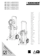
Please unfold the front picture side
1 Nozzle
2 Marking of the nozzle
3 Spray lance
4 Trigger gun
5 Safety lever
6 Lever for trigger gun
7 High pressure hose
8 Rubber band (not with appliances with 

hose drum)

9 Spray lance holder with clamping, for 

transportation

10 Power switch
11 Carrying handle
12 Quiver for spray lance
13 High pressure connection
14 Handle
15 Water connection
16 Detergent suction hose with filter and 

detergent dosing

17 Sieve
18 Hose hub
19 Union joint
20 Wheel cap

21 Skid/parking runner
22 Nozzle rack for rotor nozzle (rotor noz-

zle is only included in the scope of de-
livery with model HD...Plus)

23 Nozzle rack for triple nozzle
24 Transport bracket for surface cleaner
25 Unlocking device push handle
26 Push handle, bottom (slid in)
27 Push handle, top (extended)
28 Storage compartment for hoses
29 Cable clamp
30 Spray lance holder without clamping
31 Hose drum
32 Crank

– The operating elements for the cleaning 

process are yellow.

– The controls for the maintenance and 

service are light gray.

– Before first start-up it is definitely nec-

essary to read the operating instruc-
tions and safety indications Nr. 5.951-
949.0!

– Please follow the national rules and 

regulations for fluid spray jets of the re-
spective country.

– Please follow the national rules and 

regulations for accident prevention of 
the respective country. Fluid spray jets 
must be tested regularly and the results 
of these tests must be documented in 
writing.

DANGER

Pointer to immediate danger, which leads 
to severe injuries or death.

WARNING

Pointer to a possibly dangerous situation, 
which can lead to severe injuries or death.

CAUTION

Pointer to a possibly dangerous situation, 
which can lead to minor injuries.
ATTENTION
Pointer to a possibly dangerous situation, 
which can lead to property damage.

Contents

Device elements . . . . . . . . . . .  EN

1

Safety instructions. . . . . . . . . .  EN

1

Proper use  . . . . . . . . . . . . . . .  EN

2

Safety Devices  . . . . . . . . . . . .  EN

2

Environmental protection  . . . .  EN

2

Before Startup. . . . . . . . . . . . .  EN

3

Start up . . . . . . . . . . . . . . . . . .  EN

3

Operation  . . . . . . . . . . . . . . . .  EN

4

Transport. . . . . . . . . . . . . . . . .  EN

5

Storage . . . . . . . . . . . . . . . . . .  EN

6

Maintenance and care  . . . . . .  EN

6

Troubleshooting  . . . . . . . . . . .  EN

6

Accessories and Spare Parts .  EN

7

Warranty . . . . . . . . . . . . . . . . .  EN

7

EC Declaration of Conformity .  EN

8

Technical specifications  . . . . .  EN

9

Device elements

Colour coding

Safety instructions

Hazard levels

18

EN

Summary of Contents for HD 5/12 C

Page 1: ...3790 11 14 Deutsch 6 English 18 Fran ais 30 Italiano 42 Nederlands 54 Espa ol 66 Portugu s 78 Dansk 90 Norsk 101 Svenska 112 Suomi 123 134 T rk e 147 159 Magyar 172 e tina 184 Sloven ina 196 Polski 20...

Page 2: ...4...

Page 3: ...5...

Page 4: ...the cleaning process are yellow The controls for the maintenance and service are light gray Before first start up it is definitely nec essary to read the operating instruc tions and safety indications...

Page 5: ...fety devices serve for the protection of the user and must not be put out of opera tion or bypassed with respect to their func tion If the lever on the trigger gun is released the pressure switch turn...

Page 6: ...to a socket WARNING Observe regulations of water supplier According to applicable regula tions the appliance must never be used on the drinking water net without a system separator A suit able system...

Page 7: ...gun and pull the lever of the gun Close the hand spray gun Turn the casing of the nozzle till the de sired symbol matches the marking WARNING Unsuitable detergents can cause damage to the appliance an...

Page 8: ...TENTION Frost will destroy the not completely water drained device Store the appliance in a frost free area Drain water Pump in conventional frost protection agents through the appliance Note Use norm...

Page 9: ...take advice on this matter Check connection cable for damages risk of electrical shock get the dam aged connection cable replaced imme diately by an authorised customer ser vice person electrician Ch...

Page 10: ...gent filter Check clean detergent suction hose with filter Contact Customer Service if needed Only use accessories and spare parts which have been approved by the man ufacturer The exclusive use of or...

Page 11: ...14 2212 Winnenden 2013 09 01 EC Declaration of Conformity Product High pressure cleaner Type 1 520 xxx Relevant EU Directives 2006 42 EC 2009 127 EC 2004 108 EC 2000 14 EC Applied harmonized standards...

Page 12: ...r 20 C m 0 5 Max feed pressure MPa 1 Performance data Working pressure MPa 12 12 11 5 Nozzle size 035 035 038 Max operating over pressure MPa 17 5 17 5 17 1 Water flow rate I min 8 3 Detergent suck in...

Page 13: ...ure MPa 1 Performance data Working pressure MPa 11 5 12 13 Nozzle size 038 036 034 Max operating over pressure MPa 17 1 18 17 5 Water flow rate I min 8 3 Detergent suck in l h 0 25 Max recoil force of...

Page 14: ...Pa 1 Performance data Working pressure CX MPa 15 15 17 17 16 5 17 13 13 Nozzle size 032 027 030 038 Max operating over pressure MPa 20 19 Water flow rate I min 8 3 8 1 8 0 9 8 Detergent suck in l h 0...

Page 15: ...MPa 1 Performance data Working pressure MPa 13 12 5 Nozzle size 038 042 043 Max operating over pressure MPa 19 18 Water flow rate I min 9 8 10 0 Detergent suck in l h 0 25 Max recoil force of trigger...

Page 16: ......

Page 17: ......

Page 18: ......

Page 19: ......

Page 20: ...http www kaercher com dealersearch...

Reviews: