background image

9.807-623.0  •  Rev. 10/15

OPERA

T

OR’S MANU

AL 

 PRESSURE W

ASHER 


10

SHUTTING DOWN AND CLEAN-UP

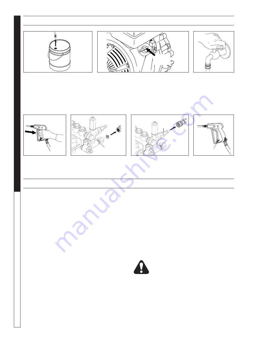
STEP 1:

 Remove detergent suc-

tion tube from container and insert 
into one gallon of fresh water. Slide 
nozzle forward for low pressure or to 
connect black detergent nozzle into 
wand quick coupler. Pull trigger on 
spray gun and siphon water for one 
minute.

STEP 2:

 Turn off the engine.

STEP 3:

 Turn off wa-

ter supply.

STEP 5:

 Disconnect the gar-

den hose from the water inlet 
on the machine.

STEP 6:

 Disconnect the high 

pressure hose from high pres-
sure outlet.

S T E P   7 :

  E n g a g e 

the spray gun safety 
lock.

STEP 4:

 Press trigger 

to release water pres-
sure.

CAUTION: Always store your pressure washer in a 
location where the temperature will not fall below 
32°F (0°C). The pump in this machine is susceptible 
to permanent damage if frozen. FREEZE DAMAGE 
IS NOT COVERED BY WARRANTY.

  1.  Stop the pressure washer, squeeze spray gun trig-

ger to release pressure.

 2. Detach water supply hose and high pressure hose.
  3.  Turn on the machine for a few seconds, until  re-

maining water exits. Turn engine off immediately.

  4.  Drain the gas and oil from the engine.
  5. Do not allow high pressure hose to become 

kinked.

  6.  Store the machine and accessories in a room which 

does not reach freezing temperatures.

CAUTION: Failure to follow the above directions will 
result in damage to your pressure washer.

When the pressure washer is not being operated or is 
being stored for more than one month, follow these 
instructions:
  1.  Replenish engine oil to upper level.
  2.  Drain gasoline from fuel tank, fuel line, fuel valve 

and carburetor.

  3.  Pour about one teaspoon of engine oil through the 

spark plug hole, pull the starter grip several times 
and replace the plug. Then pull the starter grip 

slowly until you feel increased pressure which in-
dicates the piston is on its compression stroke and 
leave it in that position. This closes both the intake 
and exhaust valves to prevent rusting of cylinder.

  4.  Cover the pressure washer and store in a clean, 

dry place that is well ventilated away from open 
fl ame  or sparks. 

NOTE: 

The use of a fuel additive, 

such as STA-BIL

®

, or an equivalent, will minimize 

the formulation of fuel deposits during shortage. 
Such additives may be added to the gasoline in 
the fuel tank of the engine, or to the gasoline in a 
storage container.

After Extended Storage

CAUTION: Prior to restarting, thaw out any 
possible ice from pressure washer hoses, 
spray gun or wand.

Engine Maintenance

During the winter months, rare atmospheric conditions 
may develop which will cause an icing condition in the 
carburetor. If this develops, the engine may run rough, 
lose power and may stall. This temporary condition can 
be overcome by defl ecting some of the hot air from the 
engine over the carburetor area. 

 NOTE:

 Refer to the 

engine manufacturer's manual for service and main-
tenance of the engine.

STORAGE

Pump Water 

Inlet

High Pressure 

Outlet

Safety Latch

On-Off
Switch

Summary of Contents for HD 3.0/30 Pb

Page 1: ... MODEL ORDER HD 3 0 30 Pb 1 575 152 0 HD 3 7 35 Pb 1 575 154 0 HD 3 0 40 Pb 1 575 155 0 OPERATOR S MANUAL To locate your local Kärcher Commercial Pressure Washer Dealer nearest you visit www karchercommercial com ...

Page 2: ...nformation 3 4 Component Identification 5 Assembly Instructions 6 Operating Instructions 7 8 Detergents Cleaning Techniques 9 Shut Down and Clean Up 10 Storage 10 Troubleshooting 11 Adjusting Unloader Valves 11 Preventative Maintenance 12 Oil Change Record 12 Models 152 0 154 0 155 0 Exploded View 13 Models 152 0 154 0 155 0 Exploded View Parts List 14 15 Specifications 16 17 Hose and Spray Gun As...

Page 3: ...h local codes Contact your electrician plumber utility company or the selling distributor for specific details WARNING RISK OF ASPHYXIATION USE THIS PRODUCT ONLY IN A WELL VENTILATED AREA WARNING Risk of asphyxiation Use this product only in a well ventilated area 5 Avoid installing machines in small areas or near exhaust fans Exhaust contains poi sonous carbon monoxide gas exposure may cause loss...

Page 4: ...e devel oped by these machines will cause personal injury or equip ment damage Keep clear of nozzle Use caution when oper ating Do not direct discharge stream at people or severe in jury or death will result 13 Never make adjustments on machine while in operation 14 Be certain all quick coupler fittings are secured before using pressure washer WARNING PROTECT FROM FREEZING WARNING Protect machine ...

Page 5: ...onnected to the spray gun High Pressure Hose Connect one end to water pump discharge nipple detergent injector nipple and the other end to spray gun Note If trigger on spray gun is released for more than 1 2 minutes water may leak from pump protec tor Warm water will discharge from pump protector onto floor This system prevents internal pump damage from high temperatures Starter Grip High Pressure...

Page 6: ...locks Pull the nozzle to make sure it is secure STEP 7 Connect high pressure hose to pump discharge fitting Push coupler collar forward until secure STEP 5 Pull the spring loaded collar of the wand coupler back to insert your choice of pressure nozzle STEP 8 Connect garden hose to a clean cold water source and open supply valve completely NEVER use hot water ASSEMBLY INSTRUCTIONS STEP 9 Connect th...

Page 7: ...Check pump oil level by using dipstick or observe oil level in oil window if equipped Use 30 wt non detergent oil STEP 5 Move the fuel shut off valve to the On posi tion When the engine is not in use leave the fuel valve in the OFF position STEP 4 Trigger the spray gun to eliminate trapped air then wait for a steady flow of water to emerge from the spray nozzle OPERATING INSTRUCTIONS STEP 3 Fill g...

Page 8: ...o fast position CAUTION Small engines may kick back Do not hold pull starter grip tightly in hand OPERATING INSTRUCTIONS CONT The five color coded quick connect nozzles provide a wide array of spray widths from 0 to 40 and are easily accessible when placed in the convenient rubber nozzle holder which is provided on the front of the machine NOTE For a more gentle rinse select the white 40 or green ...

Page 9: ...CLEANING TIPS Pre rinse cleaning surface with fresh water Place de tergent suction tube directly into cleaning solution and apply to surface at low pressure for best results limit your work area to sections approximately 6 feet square and always apply detergent from bottom to top Allow detergent to remain on surface 1 3 minutes Do not al low detergent to dry on surface If surface appears to be dry...

Page 10: ... the pressure washer is not being operated or is being stored for more than one month follow these instructions 1 Replenish engine oil to upper level 2 Drain gasoline from fuel tank fuel line fuel valve and carburetor 3 Pour about one teaspoon of engine oil through the spark plug hole pull the starter grip several times and replace the plug Then pull the starter grip slowly until you feel increase...

Page 11: ...eplace as needed Slow engine RPM Set engine speed at proper specifications Pump sucking air Check water supply and possibility of air seepage Valves sticking Check and clean or replace if necessary Unloader valve seat faulty Check and replace if necessary FLUCTUATING PRESSURE Valves worn Check and replace if necessary Blockage in valve Check and replace if necessary Pump sucking air Check water su...

Page 12: ...nce Regular preventative maintenance will add many hours to the life of your pressure washer Perform maintenance more often under severe conditions Maintenance Operation Every 8 Hrs or Daily 25 Hrs or Weekly 50 Hrs or Monthly 100 Hrs or Yearly Yearly Check Oil Pump X Engine X Change Oil Pump X Engine X Air Cleaner Check Clean Spark Plug X Check Valve Clearance X Fuel Tank Filter X Water Filter Cle...

Page 13: ...act Loca l Fire Agen cies for Laws or Regu lation s Relat ing to Fire Preve ntion Requ ireme nts WA RN IN G 8 917 0 15 0 EXPLODED VIEW 1 575 152 0 154 0 155 0 17 18 9 10 11 12 10 11 16 13 15 31 19 27 29 6 28 30 1 59 58 58 2 3 4 6 5 57 40 41 42 45 43 39 38 37 32 36 32 35 44 34 49 51 25 24 60 61 54 11 14 47 52 50 48 23 56 55 59 22 21 53 11 20 10 63 33 58 58 20 46 28 28 28 62 61 60 61 60 6 58 59 57 1...

Page 14: ...nt 1 Non Adj 3 5 GPM 0 083 35 9 802 254 0 Hose 1 4 Push On 1 ft Fuel Line All except 155 0 36 8 706 958 0 Barb 1 4 Barb x 1 4 ML Pipe 1 90 All Except 155 0 ITEM PART NO DESCRIPTION QTY 37 8 706 955 Hose Barb 1 4 Barb x 1 8 1 ML Pipe 90 All Except 155 0 154 0 8 706 940 0 Hose Barb 1 4 Barb x 1 8 1 ML Pipe 154 0 38 9 802 190 0 Valve E Z Start 1 3 8 MPT x 1 8 FPT 9 804 065 0 Valve E Z Start 1 1 4 MPT...

Page 15: ...0 0 Unloader VRT3 Ez Start 155 0 1 72 9 802 870 0 Block Unloader 1 3 8 x 3 8 1 25 Steel 155 0 73 9 802 728 0 Bolt 3 8 x 2 NC HH 155 0 2 74 9 802 807 0 Washer 3 8 SAE Flat 155 0 2 75 9 197 003 0 Nut 3 8 ESNA NC 155 0 2 76 8 705 974 0 Nipple 3 8 Hex Steel 155 0 1 77 9 802 129 0 Elbow 3 8 x 1 2 JIC 155 0 1 78 8 706 860 0 Street Tee 1 2 155 0 1 79 9 802 128 0 Nipple 1 2 x 1 2 JIC 155 0 1 80 9 802 259 ...

Page 16: ...o Pump Pulley Pump Pulley Part No 1 575 152 0 3 0 3000 3 5 KD3030 9 804 006 0 9 175 018 0 GX270 270cc 8 750 680 0 2BK80 9 802 389 0 1 575 154 0 3 7 3500 4 0 KM4035R 3 8 751 189 0 9 175 018 0 GX390 390cc 8 750 580 0 2BK90H 8 715 593 0 1 575 155 0 3 0 4000 3 0 KM3540R 3 8 751 186 0 8 750 300 0 GX390 390cc 8 750 580 0 2BK80H 9 802 389 0 SPECIFICATIONS ...

Page 17: ...No Engine Bushing Bushing Part No Belt Size Belt Part No 1 575 152 0 24MM 9 802 402 0 2BK40H 9 802 384 0 HX1 9 802 398 0 BX38 2 9 802 417 0 1 575 154 0 24MM 9 802 402 0 2BK32H 9 802 381 0 HX1 9 802 398 0 BX39 2 9 802 418 0 1 575 155 0 24MM 9 802 402 0 2BK40H 9 802 384 0 HX1 9 802 398 0 BX38 2 9 802 417 0 SPECIFICATIONS ...

Page 18: ...e Breakdown for Part Numbers 5 8 739 125 0 Hose 3 8 x 50 1 Wire Tuff Flex 150 0 151 0 152 0 1 8 739 203 0 Hose 3 8 x 50 2 Wire Tuff Flex 154 0 155 0 1 6 9 802 166 0 Coupler 3 8 Female Brass 1 7 9 802 216 0 Injector Chemical Non Adjust 3 5 GPM 083 1 8 6 390 126 0 Clamp Hose 2 9 9 802 251 0 Tube 1 4 x 1 2 Clear Vinyl 6 ft 10 8 707 057 0 TStrainer Plastic 1 4 Hose Barb 1 11 9 802 170 0 Nipple 3 8 x 3...

Page 19: ... nut Item 19 onto the stem Item 3 until the threads cut into the nylon insert of the lock nut Item 19 If adjustment knob Item 24 DOES NOT make contact with upper nut Items 20 remove adjusting knob Item 24 re adjust raise nuts Items 20 on stem Item 3 and re attach adjustment knob Item 24 then repeat step 6 If adjustment knob Item 24 DOES make contact with upper nut release the trigger of the spray ...

Page 20: ...18 9 802 925 0 Brass Plug 3 8 2 ITEM PART NO DESCRIPTION QTY 23 9 802 944 0 Hexagonal Screw 8 24 8 717 210 0 Closed Bearing Housing 1 25 9 803 192 0 O Ring Ø1 78 x 60 05 2 26 8 933 011 0 Tapered Roller Bearing 2 27 9 803 146 0 Crankshaft 3540 1 9 803 147 0 Crankshaft 4035 1 28 9 803 167 0 Crankshaft Key 1 29 9 802 921 0 Oil Dip Stick 1 30 9 803 140 0 Crankshaft Seal 1 31 9 803 178 0 Shim 2 32 8 71...

Page 21: ...4 1 48 9 802 939 0 Cover Screw 5 Available in kit See below REPAIR KIT NO 8 725 360 0 8 725 358 0 8 725 361 0 8 725 359 0 8 725 237 0 8 933 023 0 9 802 603 0 9 802 609 0 KIT DESCRIPTION Plunger Seal 4035 18mm Plunger Seal 3540 15mm Complete Seal Packing 4035 18mm Complete Seal Packing 3540 15mm Plunger 4030 18mm Plunger 3540 15mm Complete Valve Plunger Oil Seals ITEM NUMBERS INCLUDED 3 5 7 3 5 7 3...

Page 22: ...www karchercommercial com Form 9 807 623 0 Revised 10 15 Printed in U S A or Mexico ...

Reviews: