
English
5.905-945.0 Rev. 00 (06/15)
29
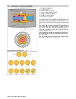
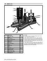
When working on the device, please always use the cur-
rent circuit diagram in DISIS.
11
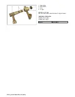
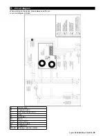
Circuit diagram
A1
Control chip
B1
Pressure switch
D1
Operating display (LED)
F1
Fuse
K1
Contactor
M1
Motor
Q1/S1
Power switch
Q2
Pressure switch
T1
Transformer
WS_M1
Winding protection contact