background image

7

1. Press down on the latch to open the battery cover.

2. Insert a fully charged Li-Ion 

   battery according to the polarity 

   diagram on the inside of the 

   battery cover.

3. Close the battery cover. 

4. Can be charged with any  5V 

   charger and Type-C USB cable.

1. Press down on the latch and open the battery cover.

2. Insert 3 new AA batteries of the same brand according to    

   the polarity diagram on the inside of the battery cover.

3. Close the battery cover.

 Lithium-Ion Battery (optional) Installation 

BATTERY INSTALLATION & SAFETY 

Summary of Contents for Prolaser 852G

Page 1: ...User Manual Manual del usuario Manuel d utilisation Prolaser Cross Line Laser Model No 852G...

Page 2: ...he most out of your laser tool APPLICATIONS The852GGREENProlaser CrossLineisinnovatively designed for a very broad range of professional and DIY jobs including Aligning tiles cabinets borders moldings...

Page 3: ...3 Features 4 Safety instructions 5 6 Battery installation Safety 7 8 Overview 9 Operating instructions 10 12 Maintenance 13 Field calibration test 14 19 Specifications 20 Warranty 21 CONTENTS...

Page 4: ...t can be detected by a detector The max detectable range of the laser in pulse mode is 40m 130 Manual mode allows angular layout marking Locking mechanism to protect the pendulum during transportation...

Page 5: ...into a laser beam using magnifying optical devices such as binoculars or a telescope as this will increase the level of eye injury WARNING This product contains lead in solder and certain Electrical...

Page 6: ...above 45 C 14 F 113 F Do not operate the laser in explosive atmospheres such as flammable liquids gases or dust sparks from the tool can cause ignition When not in use turn off the power engage the pe...

Page 7: ...y cover 3 Close the battery cover 4 Can be charged with any 5V charger and Type C USB cable 1 Press down on the latch and open the battery cover 2 Insert 3 new AA batteries of the same brand according...

Page 8: ...ries 4 Do not dispose of batteries into household waste 5 Do not dispose batteries in fire 6 Defective or dead batteries must be disposed according to local regulations 7 Keep the batteries out of rea...

Page 9: ...9 1 On Off Locking Switch 2 Keypad a Pulse Mode button b Beam Selector button c Manual Mode button 3 Laser output window 4 Battery cover 5 tripod mount OVERVIEW...

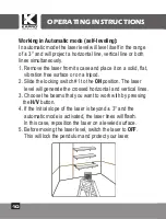
Page 10: ...2 Slide the locking switch 1 to the ON position The laser level will generate the crossed horizontal and vertical lines 3 Choose the beams that you want to work with by pressing the H V button 4 If t...

Page 11: ...he Manual push button mode M The laser will project the cross lines 2 Choose the beams that you want to work with by pushing the Beam Selector push button H V 3 To mark a slope tilt the laser using to...

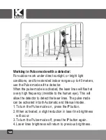
Page 12: ...ser lines will flash at a very high frequency invisible to the human eye This will allow the detector to detect the laser lines The pulse mode can be activated in both Automatic and Manual modes 1 To...

Page 13: ...th a clean soft cloth Do not use solvents Although the laser level is dust and dirt resistant to a certain degree do not store in dusty places as a long term exposure may damage internal moving parts...

Page 14: ...heck the leveling accuracy of the vertical line Checking the Height Accuracy of the Horizontal Line Up and down deviation 1 Set up the laser on a tripod or on a solid surface between two walls A and B...

Page 15: ...180 towards wall B and mark on the wall the center of the cross lines as b1 see figure 2 6 Move the laser level towards wall B and position it approximately 0 5 meter from wall B 7 Mark on wall B the...

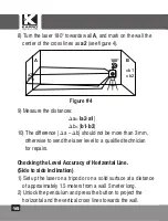
Page 16: ...se to send the laser level to a qualified technician for repairs Checking the Level Accuracy of Horizontal Line Side to side inclination 1 Set up the laser on a tripod or on a solid surface at a dista...

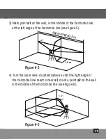
Page 17: ...ft edge of the horizontal line see figure 5 4 Turn the laser level counterclockwise until the right edge of the horizontal line reach s near a1 mark a point a2 on the wall in the middle of the horizon...

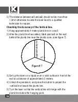
Page 18: ...plumb line has settled Mark point a1 on the wall behind the plumb line near the plumb cone see figure 7 3 Set up the laser on a tripod or on a solid surface in front of the wall at a distance of appr...

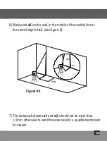
Page 19: ...n the middle of the vertical line at the same height of a1 see figure 8 7 The distance between a1 and a2 should not be more than 1 5mm otherwise to send the laser level to a qualified technician for r...

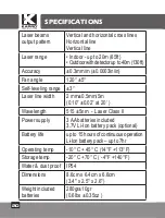
Page 20: ...line width 2 mm 0 5mm 5m 0 10 0 02 at 20 Wavelength 515 5nm Laser Class II Power supply 3 AA batteries included 3 7V Li Ion battery pack optional Battery life up to 15 hours of continuous operation L...

Page 21: ...f sale of your choice for collection COSTS AND WARRANTY Products under warranty will be shipped and repaired free of charge In case of products that are not under warranty you will be notified by the...

Page 22: ...LICACIONES El 852G Prolaser Cross Line GREEN est dise ado de manera innovadora para una gama muy amplia de trabajos profesionales y de bricolaje DIY incluyendo Alineaci n de azulejos armarios bordes m...

Page 23: ...Instrucciones de seguridad 25 26 Instalaci n de bater as y Seguridad 27 28 Descripci n general 29 Instrucciones de operaci n 30 32 Mantenimiento 33 Prueba de calibraci n de campo 34 39 Especificacione...

Page 24: ...en ser detectados por un detector El alcance m ximo de detecci n del l ser en el modo de pulso es de 40m 130 El modo manual permite el trazado marcaci n angular Mecanismo de bloqueo para proteger el p...

Page 25: ...zando equipos pticos de aumento tal como prism ticos o telescopio ya que esto aumentar el nivel de lesi n ocular ADVERTENCIA Este producto contiene plomo en las soldaduras y ciertas partes el ctricas...

Page 26: ...5 C 14 F 113 F No opere el l ser en atm sferas explosivas tales como l quidos inflamables gases o polvo Las chispas de la herramienta pueden causar ignici n Cuando no est en uso apague la unidad engan...

Page 27: ...olocar la tapa de las bater as 1 Presione el pestillo para abrir la tapa de la bater a 2 Inserte una bater a de iones de litio completamente cargada de acuerdo con el diagrama de polaridad en el inter...

Page 28: ...y nuevas 4 No deseche las bater as en la basura hogare a 5 No deseche las bater as en el fuego 6 Las bater as defectuosas o gastadas deben desecharse de acuerdo con las normativas locales 7 Mantenga l...

Page 29: ...de bloqueo de encendido apagado On Off 2 Teclado a Bot n de modo manual b Bot n selector de haz c Bot n de modo pulso 3 Ventana de salida del l ser 4 Tapa de las bater as 5 Montaje de tr pode de DESC...

Page 30: ...o 1 a la posici n ON encendido el nivel l ser generar las l neas horizontales y verticales 3 Elija los rayos con los que desea trabajar presionando el bot n pulsador de rayos H V 4 Si la pendiente ini...

Page 31: ...el bot n pulsador de modo Manual M El l ser proyectar las l neas cruzadas 2 Elija los rayos con los que desea trabajar presionando el bot n pulsador de selecci n de rayos H V 3 Para marcar una pendie...

Page 32: ...neas de l ser parpadear n a muy alta frecuencia invisible para el ojo humano esto permitir que el detector detecte las l neas de l ser 1 El modo de pulsos puede ser activado en los modos autom tico y...

Page 33: ...ando un pa o suave y limpio No utilice disolventes Aunque el nivel l ser es resistente al polvo y la suciedad en cierta medida no lo almacene en lugares polvorientos ya que una exposici n de largo pla...

Page 34: ...n de nivelaci n de la l nea vertical Comprobaci n de la precisi n de altura de la l nea horizontal desviaci n hacia abajo y hacia arriba 1 Instale el l ser sobre un tr pode o sobre una superficie s li...

Page 35: ...a pared el centro de las l neas cruzadas como b1 ver la figura 2 6 Mueva el nivel l ser hacia la pared B y posici nelo aproximadamente a 0 5 metros de la pared B 7 Marque en la pared B el centro de la...

Page 36: ...r a un t cnico cualificado para su reparaci n Comprobaci n de la precisi n de nivelado de la l nea horizontal Inclinaci n de lado a lado 1 Instale el l ser sobre un tr pode o sobre una superficie s li...

Page 37: ...izquierdo de la l nea horizontal ver la figura 5 4 Gire el nivel l ser en sentido contrario de las manecillas del reloj hasta que el borde derecho de la l nea horizontal llegue cerca de a1 marque un p...

Page 38: ...arque el punto a1 en la pared detr s de la l nea de plomada cerca del cono de la plomada ver la figura 7 3 Instale el l ser sobre un tr pode o sobre una superficie s lida frente a la pared a una dista...

Page 39: ...en el medio de la l nea vertical a la misma altura de a1 ver la la figura 8 7 La distancia entre a1 y a2 no debe ser de m s de 1 5 mm si no es as env e el nivel l ser a un t cnico cualificado para su...

Page 40: ...e l nea l ser 2 mm 0 5mm 5m Longitud de onda 515 5nm L ser de Clase II Fuente de alimentaci n 3 bater as AA 3 7V la bater a de iones de litio opcional Duraci n de la bater a 15 horas de funcionamiento...

Page 41: ...ado el producto ser devuelto a un punto de venta de su elecci n para su recogida COSTOS Y GARANT A Los productos bajo garant a ser n enviados y reparados sin costo En caso de productos que no est n en...

Page 42: ...de votre outil laser APPLICATIONS Deconceptioninnovante le852GProlaser CrossLineGREEN se destine de tr s nombreuses t ches professionnelles ou de bricolage notamment Alignement de carrelage placards r...

Page 43: ...Fonctions 44 Consignes de s curit 45 46 Installation des piles et s curit 47 48 Vue d ensemble 49 Utilisation 50 52 Entretien 53 Test d talonnage sur site 54 59 Caract ristiques 60 Garantie 61 CONTEN...

Page 44: ...d tecteur La port e d tectable maximale du laser en mode impulsion est de 40 m tres 130 Mode manuel pour le tra age et le marquage d angle Syst me de verrouillage de protection du balancier durant le...

Page 45: ...aser avec un mat riel optique grossissant des jumelles ou un t lescope par exemple pouvant aggraver les l sions oculaires ATTENTION Ce produit contient des soudures au plomb et certaines pi ces lectri...

Page 46: ...rieures 45 C 14 F 113 F Ne pas utiliser en environnement inflammable tel qu en pr sence de liquides gaz ou poussi res inf ammables Les tincelles de l outil sont inflammables Lorsqu il n est pas utilis...

Page 47: ...e couvercle de piles 1 Ouvrir le couvercle de la pile en appuyant sur le loquet 2 Ins rez une pile Li Ion compl tement charg e conform ment au sch ma de polarit affich sur la face int rieure du couver...

Page 48: ...ger des piles neuves et anciennes 4 Ne pas jeter les piles aux ordures m nag res 5 Ne pas jeter les piles au feu 6 Les piles d fectueuses ou usag es doivent tre mises au rebut conform ment la r glemen...

Page 49: ...pteur On Off 2 Bloc de touches a Bouton de mode manuel b Bouton de s lection de faisceau c Bouton de mode impulsion impulsion 3 Fen tre de projection laser 4 Couvercle de piles 5 Adaptateur tr pied VU...

Page 50: ...sur la position MARCHE Le niveau laser g n rera les lignes horizontales et verticales crois es 3 Choisissez les faisceaux avec lesquels vous voulez travailler en appuyant sur le bouton poussoir des fa...

Page 51: ...u Mode manuel M Le laser projettera les lignes transversale s 2 Choisissez les faisceaux avec lesquels vous voulez travailler en appuyant sur le bouton poussoir de s lection des faisceaux H V 3 Pour m...

Page 52: ...rsque le mode puls est activ les lignes laser clignotent tr s haute fr quence invisible l il humain ce qui permet au d tecteur de d tecter les lignes laser 1 Le mode puls peut tre activ en modes autom...

Page 53: ...un chiffon propre et doux N utilisez pas de solvants Bien que le niveau laser soit r sistant l eau et la poussi re ne le remisez pas en un endroit poussi reux une longue exposition tant susceptible d...

Page 54: ...n la pr cision de nivellement de la ligne verticale V rification de la pr cision de hauteur de la ligne horizontale cart haut bas 1 Posez le laser sur un tr pied ou une surface solide entre deux murs...

Page 55: ...rs le mur B et marquez sur le mur le centre des lignes crois es comme point b1 voir illustration 2 6 D placez le niveau laser face au mur B environ 50 cm du mur 7 Marquez sur le mur B le croisement de...

Page 56: ...s contraire le niveau laser doit tre examin par un technicien agr V rification de la pr cision de nivellement de la ligne horizontale inclinaison lat rale 1 Placez le laser sur un tr pied ou une surfa...

Page 57: ...horizontale voir illustration 5 4 Tournez le niveau laser dans le sens antihoraire jusqu ce que l extr mit droite de la ligne horizontale soit au niveau de a1 et marquez le point a2 sur le mur sur la...

Page 58: ...omb en quilibre marquez le point a1 sur le mur derri re le fil plomb c t du plomb voir illustration 7 3 Placez le laser sur un tr pied ou une surface solide face au mur une distance d environ 2 m tres...

Page 59: ...z le point a2 au milieu de la ligne verticale et la m me hauteur que a1 voir illustration 8 7 La distance entre a1 et a2 ne doit pas exc der 1 5 mm dans le cas contraire le niveau laser doit tre exami...

Page 60: ...Largeur de ligne laser 2 mm 0 5mm 5 m tres Longueur d onde 515 5nm Laser de classe 2 Alimentation 3 piles AA 3 7V la batterie au lithium ion en option Autonomie 15 heures de fonctionnement continu la...

Page 61: ...3 Une fois la r paration termin e le produit sera renvoy au point de vente de votre choix pour y tre r cup r CO TS ET GARANTIE Les produits sous garantie seront exp di s et r par s gratuitement Pour l...

Page 62: ...62 Kapro 852G Prolaser Cross Line Laser 852G Prolaser Cross Line Laser GREEN RU...

Page 63: ...63 64 65 66 67 68 69 70 72 73 74 79 80 81...

Page 64: ...64 40 130 1 4...

Page 65: ...65 II EN 60825 1 25249 6 65...

Page 66: ...66 10 C 45 C...

Page 67: ...67 1 2 3 3 1 2 3 4 5 USB Type C...

Page 68: ...68 1 2 3 4 5 6 7...

Page 69: ...69 1 2 a b c 3 4 5...

Page 70: ...70 3 1 2 1 ON 3 H V 4 3 5 1 OFF...

Page 71: ...71 1 M 2 H V 3 4 M 5 1...

Page 72: ...72 40 1 2 P 3 4 P...

Page 73: ...73...

Page 74: ...74 B A a1 0 5 m x Kapro 1 5 2 0 5 3 4 a1 1 5 0 5 1...

Page 75: ...75 B A a1 b2 x b1 x x 0 5 m B A a1 b1 x x 180 5 180 B b1 2 6 0 5 B 7 b2 3 2 3 0 5...

Page 76: ...76 8 180 2 4 9 a a2 a1 b b1 b2 10 a b 3 1 1 5 5 2 4 B A a1 b1 x b2 x x a2x 180...

Page 77: ...77 1 5 m a1 x 3 a1 5 4 a1 2 6 1 5 5 5 6 x a1 x a2...

Page 78: ...78 5 a1 a2 1 5 1 4 2 a1 7 3 2 4 5 7 4 a1 x...

Page 79: ...79 2 m a1 a2 x x x 6 2 a1 8 7 a1 a2 1 5 2 8...

Page 80: ...80 20 40 0 3 120 5 3 2 0 5 5 515 5 II 3 AA 3 7V 15 7 10 C 45 C 20 C 60 C IP54 8 6cm x 6 4cm x 6 6cm 280 10...

Page 81: ...81 Kapro 1 2 3 CEM 2014 30 EU 2014 35 EU 852G 2014 30 EU 2011 65 EU EN60825 1 2014 EN61326 1 2013...

Page 82: ...82...

Page 83: ...83...

Page 84: ...84 Rev 2 0 2023 Kapro Industries Ltd...

Reviews: