Kanomax 3900 Operation Manual Download Page 1


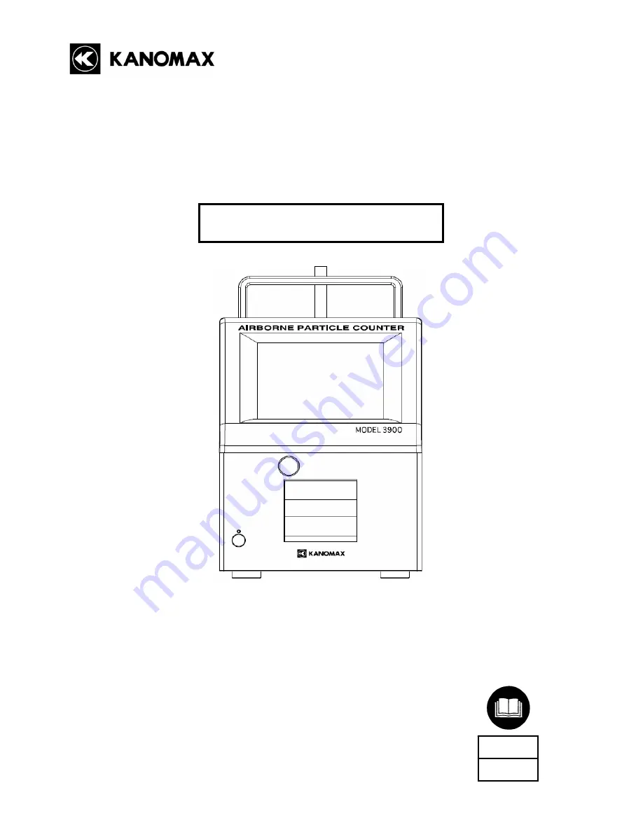
Airborne Particle Counter 

MODEL 3900


Please read this operation manual carefully and


understand the warnings described within


before operating this instrument. 

Keep this manual handy for future reference.


03001

08.09


Operation Manual

www.actoolsupply.com

www.actoolsupply.com

Summary of Contents for 3900

Page 1: ... Please read this operation manual carefully and understand the warnings described within before operating this instrument Keep this manual handy for future reference 03001 08 09 Operation Manual www actoolsupply com www actoolsupply com ...

Page 2: ... CF Card 512MB installed in the instrument 1 Make sure to use the designated fuse specified below for proper operation Manufacturer Littlefuse Model Name 0217002 MXP Optional Extras ITEM MODEL QTY Carrying Case 3900 21 1 Lithium ion Battery BSA2 06 1 Battery Charger BSA2 10 1 Air Velocity Probe 0843 1 Temperature and Humidity Probe 0844 1 Differential Pressure Sensor C264 0 100Pa 1 Differential Pr...

Page 3: ...ar the symbol WARNING Do not disassemble modify or repair the instrument A 3B laser diode is used as the optical source inside the instrument Therefore never attempt to disassemble the instrument as it is extremely dangerous Also disassembling the unit may result in short circuit and malfunction Use the instrument properly by carefully following this operation manual Misuse of the instrument may r...

Page 4: ...amage to the instrument Do not perform measurements in environments exceeding the specified temperature and RH levels of the instrument The instrument should not be exposed to direct sunlight for prolonged period The instrument may not function properly outside the specified environment 10 40 C 20 85 RH non condensing Do not wipe the instrument with volatile solvents The body may be deformed or de...

Page 5: ... 3 5 2 STAT 13 3 5 3 STANDARD 17 3 5 4 Interlocking Operations 22 3 6 CONFIG 23 3 6 1 SINGLE 23 3 6 2 SEQUENCE 24 3 6 3 INTERVAL 25 3 6 4 REPEAT 26 3 6 5 STAT 27 3 6 6 STANDARD 29 3 7 FILE 31 3 8 PRESET 32 3 9 MENU 33 3 9 1 CHART 33 3 9 2 OPTION 34 3 9 3 HARDWARE 40 3 9 4 SYSTEM 42 3 9 5 REMOTE 45 3 9 6 SHUTDOWN 45 3 9 7 EXIT 45 4 Connecting Optional Extras 46 4 1 Connecting Optional Extras 46 5 P...

Page 6: ...5 1 6 STANDARD 51 6 Battery Charge 52 6 1 Charging Battery 52 7 Main Specifications 53 8 Troubleshooting 54 9 Warranty and After sales Service 56 www actoolsupply com www actoolsupply com ...

Page 7: ...sing this button Outlet Filtered sample air is exhausted at this port Do not block the pump as it may result in the damage to the instrument Optional Sensor Connecting Terminal Terminal to connect the optional sensor Refer to 4 Connecting Optional Extras for details Battery Compartment Insert rechargeable battery here Refer to 2 1 Power Supply for how to install the battery Main Power Switch For A...

Page 8: ... 90 degrees Use a coin or something similar to turn it easily Connect the battery to the connecter for rechargeable battery inside the compartment To install the battery align the notch in the battery socket with the notch on the instrument s battery connector cable Insert the battery as shown on the right picture the connecter end should go to the rear of the compartment and turn the knob back to...

Page 9: ... of the tube is not critical However make sure that the tube is not bent Approx 60cm Follow the above procedure in order to prevent all particles from entering the instrument Perform a measurement for one minute and then perform Zero Check Refer to 3 3 MONITOR for the operation method Perform Zero Check at least once a day It is recommended a Zero Check be done before and after each measurement 2 ...

Page 10: ...3 Display Description and Operation Procedure 3 1 Boot Screen A few seconds after the instrument is turned ON the screen on the left will be displayed The system is initializing Please wait for a few moments www actoolsupply com www actoolsupply com ...

Page 11: ...ery second START Starts measuring in the configured mode This button becomes STOP button after sampling starts Tap STOP button to stop sampling 6 PUMP Tap PUMP button to turn ON OFF the pump manually SAVE Tap SAVE button to turn ON OFF the data storage function while sampling PRINT TAP PRINT button to turn ON OFF the data printing function while sampling Alarm Pr Tap Alarm Pr button to turn ON OFF...

Page 12: ...ay Description and Operation Procedure 6 3 2 2 Screen Change Initial Screen MENU RETURN CONFIG RETURN MODE MONITOR RETURN START RETURN RETURN FILE RETURN PRESET RETURN www actoolsupply com www actoolsupply com ...

Page 13: ...s already operating sampling will start immediately when you tap MONITOR Note that the instrument is capable of 180 hours of continuous operation While measuring tap MONITOR again A dialog will be displayed asking you if you want to stop monitoring Tap Yes to stop monitoring Note that you cannot save measurement data or display chart when you are monitoring www actoolsupply com www actoolsupply co...

Page 14: ... in every measurement mode Mode Description SINGLE MODE Perform a measurement once within the pre set time frame Example If the setting is as follows in CONFIG menu Refer to 3 6 1 SINGLE INTERVAL N A SAMPLE T 00 00 15 CYCLES N A A 15 second sample is performed Measurement Flow Delay Time For time set in START DELAY window referring to 3 9 2 OPTION Sampling Time 15sec Start Measurement Finish Measu...

Page 15: ... the setting is as follows in CONFIG menu Refer to 3 6 3 INTERVAL INTERVAL 00 01 00 SAMPLE T 00 00 15 CYCLES 20 A total of 20 samples are performed at one minute intervals Note Sampling time is 15 seconds and standby time is 45 seconds Measurement Flow Sampling Time Start Measurement Finish Measurement Wait Time STOP Interval Sampling Time 15sec The 1st Measurement The 2nd Measurement The 20th Mea...

Page 16: ...as follows ISO14644 1 International Standard Refer to ISO14644 1 ISO 14644 1 SEQUENTIAL SAMPLING International Standard Refer to ISO14644 1 FEDERAL STANDARD m The US Standard Refer to FEDERAL STANDARD 209E FEDERAL STANDARD ft The US Standard BRITISH STANDARD British Standard Refer to BS 5295 EC GMP European Standard Refer to EC GMP GB T 16292 1996 Chinese Standard Refer to GB T 16292 1996 Select a...

Page 17: ...pump will begin running After the pump has run for 10 seconds to stabilize the measurement will begin z If START DELAY is checked in CONFIG setting Upon tapping START the Delay Time configured in 3 9 2 CONTROL PANEL OPTION START DELAY begins During the last 10 seconds of that Delay Time the pump will run to stabilize after which the measurement will begin Tap STOP to stop a measurement Tap button ...

Page 18: ... Description and Operation Procedure 12 After a measurement in REPEAT mode or INTERVAL mode is finished the measurement result will be displayed REPEAT INTERVAL SEQUENCE www actoolsupply com www actoolsupply com ...

Page 19: ... running After the pump has run for 10 seconds to stabilize the measurement will begin z If START DELAY is checked in CONFIG setting Upon tapping START the Delay Time configured in 3 9 2 CONTROL PANEL OPTION START DELAY begins During the last 10 seconds of that Delay Time the pump will run to stabilize after which the measurement will begin Tap START to start a measurement Tap STOP to stop a measu...

Page 20: ...ement Tap PRINT to print a measurement result When all of the measurements are finished a measurement result will be displayed Select LOCATION to display the measurement data of the selected LOCATION POINT Tap CLOSE to stop a measurement Tap REMEASURE to perform a measurement again at the last measurement point Tap PRINT to print a measurement result at the last measurement point Every time you ta...

Page 21: ...and tap START Tap STOP to stop a measurement Tap MAGNIFY to enlarge a MAP This button will become MINIFY button Press MINIFY to display an entire MAP when a map is magnified OK and CANCEL buttons are inactive When a MAP is magnified UP DOWN LEFT and RIGHT buttons will be activated which enables you to move MAP www actoolsupply com www actoolsupply com ...

Page 22: ...d in 3 9 2 CONTROL PANEL OPTION START DELAY begins During the last 10 seconds of that Delay Time the pump will run to stabilize after which the measurement will begin Tap button while measuring to display a graph Tap STOP to stop a measurement When a measurement is finished a measurement result window will be displayed Tap NEXT to display MAP again Then the instrument waits for the next measuremen...

Page 23: ... pump will begin running After the pump has run for 10 seconds to stabilize the measurement will begin z If START DELAY is checked in CONFIG setting Upon tapping START the Delay Time configured in 3 9 2 CONTROL PANEL OPTION START DELAY begins During the last 10 seconds of that Delay Time the pump will run to stabilize after which the measurement will begin Tap STOP to stop a measurement Tap button...

Page 24: ... measurement point and wait for the next measurement Tap REMEASURE to perform a remeasurement Tap STOP to stop a measurement Tap PRINT to print a measurement result When all measurements are finished the measurement result will be displayed Select LOCATION to display the result of the specific location Tap EVAL to display an CR EVALUATION window Tap REMEASURE to perform a remeasurement Tap PRINT t...

Page 25: ...ement point and tap START Tap STOP to stop a measurement Tap MAGNIFY to enlarge a MAP This button will become MINIFY button Press MINIFY to display an entire MAP when a map is magnified OK and CANCEL buttons are inactive UP DOWN LEFT and RIGHT buttons will be activated which enables you to move MAP www actoolsupply com www actoolsupply com ...

Page 26: ...figured in 3 9 2 CONTROL PANEL OPTION START DELAY begins During the last 10 seconds of that Delay Time the pump will run to stabilize after which the measurement will begin Tap STOP to stop a measurement Tap button while measuring to display a chart After a measurement at each location is finished a measurement result will be displayed In RAW tab measurement data will be displayed In CALC tab calc...

Page 27: ... are finished the measurement result will be displayed Select LOCATION to display the result of the specific location Tap EVAL to display an evaluation screen Tap REMEASURE to perform a remeasurement Tap PRINT to print a measurement result Tap PRINT to print a measurement result Tap Close to close the window www actoolsupply com www actoolsupply com ...

Page 28: ...the data of the particular particle size Then to display data for 6 particle sizes back again tap the particle size on the screen On the screen with data of each particle size tap to switch to display a chart Tap again to go back to the display with data for 6 particle size Every time you tap the particle unit it changes in the order of p p cf p m www actoolsupply com www actoolsupply com ...

Page 29: ...nd second on the numeric keypad and tap OK Check AUTO SAVE to store data automatically Check AUTO PRINT to print data automatically Check START DELAY to use delay time prior to a measurement Tap OK to save and activate the settings Tap PRESET to display a window asking you to input PRESET NAME Tap the entry field to display the keyboard Enter the file name and tap Enter Tap OK to save the current ...

Page 30: ... save and activate the current settings Tap PRESET to display a window asking you to input PRESET NAME Tap the entry field to display the keyboard Enter the file name and tap Enter Tap OK to save the current settings including AUTO SAVE AUTO PRINT and START DELAY on the CF card In the future you can automatically load the configuration saved here as a PRESET Refer to 3 8 PRESET www actoolsupply co...

Page 31: ...t regardless of the CYCLES setting Check AUTO SAVE to store data automatically Check AUTO PRINT to print data automatically Check START DELAY to use delay time prior to a measurement Tap OK to save and activate the settings Tap PRESET to display a window asking you to input PRESET NAME Tap the entry field to display the keyboard Enter the file name and tap Enter Tap OK to save the current settings...

Page 32: ...CYCLES setting Check AUTO SAVE to store data automatically Check AUTO PRINT to print data automatically Check START DELAY to use delay time prior to a measurement Tap OK to save and activate the settings Tap PRESET to display a window asking you to input PRESET NAME Tap the entry field to display the keyboard Enter the file name and tap Enter Tap OK to save the current settings including AUTO SAVE...

Page 33: ...a MAP file is not loaded tap an entry field of SAMPLE POINT to display a numeric keypad Enter a value and tap Enter Check AUTO SAVE to store data automatically Check AUTO PRINT to print data automatically Check START DELAY to use delay time prior to a measurement Tap OK to save and activate the settings Tap PRESET to display a window asking you to input PRESET NAME Tap the entry field to display t...

Page 34: ...he Location to be changed Use UP and DOWN buttons to change the order Tap OK Then a window will be displayed asking if you want to save the new order of the Location Tap YES or NO Tap YES to set the changes and go back to CONFIG setting screen Tap NO to go back to MAP screen Tap CANCEL to discard the changes and go back to CONFIG setting screen www actoolsupply com www actoolsupply com ...

Page 35: ...e room to be measured LOCATION Input the number of measurement point CYCLES Input the measurement cycles SAMPLE T Input the sampling time The numeric value shown next to the each entry field is the minimum value based on CLASS and ROOM Tap SET to use the recommendation value In the EXTENTION tab Configure the ROOM STATUS and COMMENT settings ROOM STATUS Select either as built as rest or operationa...

Page 36: ...ap OK to save the current settings on the CF card When specifying a MAP file in SCHEDULE tap MAP button to display MAP START and STOP buttons are inactive You can change the location order Tap the Location to be changed Use UP and DOWN buttons to change the order Tap OK Then a window will be displayed asking if you want to save the new order of the Location Tap YES or NO Tap YES to set the changes...

Page 37: ...p PRINT Use MEASURE MODE to reduce the number of files displayed Select the data that you want to display and tap OK Then the data display screen will be displayed After tapping DELETE a dialog will be displayed asking you if you want to delete it or not Tap YES to delete the data file displayed Tap PRINT to print the data Tap CLOSE to close a window In STAT mode and STANDARD mode you can change t...

Page 38: ...indicates the mode type SG SINGLE MEASUREMENT SQ SEQUENCE MEASUREMENT IN INTERVAL MEASUREMENT RP REPEAT MEASUREMENT ST STAT MEASUREMENT IS STANDARD MEASUREMENT Select the item that you want to load or delete Tap OK to display the measurement screen with the selected PRESET settings MODE and CONFIG settings Tap DELETE to delete the selected PRESET setting Refer to 3 6 CONFIG for setting procedure w...

Page 39: ...OG and LINEAR In OPTION tab configure MIN and MAX setting for each sensor For each sensor you can set three different values Tap APPLY to save the setting value that is displayed in the tab Tap OK to save the setting value and close the window Tap CANCEL to discard the configure settings and the previous settings will be applied In the chart you can change the MIN and MAX values of the Y axis base...

Page 40: ...ble alarm Also enter the threshold that you want to alarm Tap entry field to display a numeric keypad Enter a value and tap Enter In the OPTION tab you can set alarm threshold for TEMERATURE HUMIDITY VELOCITY and PRESSURE Tap the entry field to display a numeric keypad Enter value and tap Enter Tap APPLY to save the setting value that is displayed at the moment Tap OK to save the setting values bo...

Page 41: ...DARD ft BRITISH STANDARD EC GMP GB T 16292 1996 Refer to page 10 for the measurement standard Tap OK to activate the setting Change the settings and tap OK Then a dialog will be displayed saying Because standard is changed standard measurement setting dialog will open Tap OK at the upper right CONFIG setting screen will be displayed Then configure the settings Refer to 3 6 6 STANDARD for setting p...

Page 42: ...rement Mode Measurement MODE will be restricted Use Preset Preset Setting will be restricted Delete Files You will not be able to delete any files Check the item that you want to restrict and tap LOCK Then enter the password If the password is entered correctly the item is locked and the LOCK button becomes UNLOCK button In order to release the restriction uncheck the item that you want to release...

Page 43: ...If the entry is properly done the password will be changed In the MESSAGE SETTING window you can choose to display or not display a message of PREPARATION and DELAY Tap OK to activate the settings Each message is PREPARATION To be displayed after the pump is ON before sampling starts DELAY To be displayed before sampling starts when START DELAY function is ON MESSAGE www actoolsupply com www actoo...

Page 44: ...a printing ON OFF Particle size to be printed out Option sensor data printing ON OFF Check CALC DATA INCLUDED to print CALC data Check the particle size of the data that you want to print out Check OPTION to output data of the option sensor IN EVAL DATA tab configure the following setting EVAL data printing ON OFF Check EVAL DATA INCLUDED to print out the EVAL data Tap APPLY to save the setting va...

Page 45: ...rocedure 39 In START DELAY window set a measurement delay time Tap the entry field to display a keyboard Enter hour minute and second and tap OK Tap OK in order to activate the setting START DELAY www actoolsupply com www actoolsupply com ...

Page 46: ...r is connected it is displayed in blue and if not it is displayed in gray To use the option sensor check USE NO USE box UNIT Set the unit for TEMPERATURE and VELOCITY For TEMEPRATURE select C or F For VELOCITY select m sec or FPM MIN MAX Set the measurable range of the sensor connected according to the spec of the each option sensor Tap the entry field to display a numeric keyboard Enter a value a...

Page 47: ...me check the check box PUMP ALWAYS ON If you check this box you can eliminate the PREPARATION time before sampling In the REMOTE MODE SETTING check START IN REMOTE MODE to activate remote mode automatically when the instrument is turned ON Enter remote address in the entry field for ID PUMP REMOTE MODE www actoolsupply com www actoolsupply com ...

Page 48: ...calendar and set the date To change the TIME tap hour minute and second using buttons Tap OK to activate the settings In LCD setting configure Power Save time and brightness setting For Power Save setting select one among 1min 2min 3min 5min 10min and 30min To configure the brightness setting move the slider from side to side Tap OK to activate the settings DATE TIME LCD www actoolsupply com www a...

Page 49: ...ting value that is displayed at the moment Tap OK to save the setting values in all the tabs and to close the window Tap CANCEL to discard the configured settings and the previous settings will be applied In the COMMUNICATION SETTING configure the setting for Ethernet connection This setting shall be configured when connecting the instrument to PC using remote console or remote mode For the HOST N...

Page 50: ...strument for a prolonged time tap accuracy may degrade Use this menu to correct the tap location Tap the center of the cross by stylus There are 5 setting locations in total After adjusting the tap location tap the screen and go back to the Stylus setting screen Tap OK to save the settings STYLUS www actoolsupply com www actoolsupply com ...

Page 51: ...city of the memory card will be displayed 3 9 5 REMOTE Change to REMOTE MODE 3 9 6 SHUTDOWN Tap SHUTDOWN A window will be displayed asking Do you want to shut down the power 5 seconds after tapping YES the instrument will shut down 3 9 7 EXIT Go back to the main screen ABOUT www actoolsupply com www actoolsupply com ...

Page 52: ...Probe Model 0843 Velocity Range 0 1m s 0 197FPM Velocity Accuracy 0 05m s 10FPM Dimension φ20 150 mm Curl Cord 0 2m Max 1 5m Pressure Transmitter Model C264 0 100Pa Pressure Range 0 100Pa Pressure Accuracy 1 F S Guaranteed Temp 5 65 C Output 4 20mA Contact Output Cable Model 3900 03 When the alarm function is ON and the threshold is exceeded the contact closes Spec Photocoupler Maximum rating 60V ...

Page 53: ...T 10 Cycles 1 Time 0 3u 0 5u 1 0u 12 00 00 8000 5000 3000 Time 3 0u 5 0u 10 0u 12 00 00 1000 500 100 Time T C H V m s P Pa 12 00 00 25 2 68 5 0 1 15 SQ20080525120000 csv Time 0 3u 0 5u 1 0u 12 00 00 8000 5000 3000 Time 3 0u 5 0u 10 0u 12 00 00 1000 500 100 Time T C H V m s P Pa 12 00 00 25 2 68 5 0 1 15 www actoolsupply com www actoolsupply com ...

Page 54: ...0 MIN 58 9 MAX 68 5 Velocity AVE 0 20 MIN 0 13 MAX 0 31 Press AVE 5 4 MIN 4 8 MAX 6 5 Time 0 3u 0 5u 1 0u 12 00 00 137 13 5 12 00 10 185 25 3 12 00 20 175 16 2 12 00 30 159 15 6 12 00 40 158 15 3 Time 3 0u 5 0u 10 0u 12 00 00 0 0 0 12 00 10 0 0 0 12 00 20 0 0 0 12 00 30 0 0 0 12 00 40 0 0 0 Time T C H V m s P Pa 12 00 00 23 5 58 9 0 31 5 2 12 00 10 27 5 68 5 0 25 4 8 12 00 20 25 5 62 8 0 15 6 5 12...

Page 55: ... MIN 58 9 MAX 68 5 Velocity AVE 0 20 MIN 0 13 MAX 0 31 Press AVE 5 4 MIN 4 8 MAX 6 5 Time 0 3u 0 5u 1 0u 12 00 00 137 13 5 12 00 05 185 25 3 12 00 10 175 16 2 12 00 15 159 15 6 12 00 20 158 15 3 Time 3 0u 5 0u 10 0u 12 00 00 0 0 0 12 00 05 0 0 0 12 00 10 0 0 0 12 00 15 0 0 0 12 00 20 0 0 0 Time T C H V m s P Pa 12 00 00 23 5 58 9 0 31 5 2 12 00 05 27 5 68 5 0 25 4 8 12 00 10 25 5 62 8 0 15 6 5 12 ...

Page 56: ...MIN 58 9 MAX 68 5 Velocity AVE 0 20 MIN 0 13 MAX 0 31 Press AVE 5 4 MIN 4 8 MAX 6 5 Time 0 3u 0 5u 1 0u 12 00 00 137 13 5 12 00 05 185 25 3 12 00 10 175 16 2 12 00 15 159 15 6 12 00 20 158 15 3 Time 3 0u 5 0u 10 0u 12 00 00 0 0 0 12 00 05 0 0 0 12 00 10 0 0 0 12 00 15 0 0 0 12 00 20 0 0 0 Time T C H V m s P Pa 12 00 00 23 5 58 9 0 31 5 2 12 00 05 27 5 68 5 0 25 4 8 12 00 10 25 5 62 8 0 15 6 5 12 0...

Page 57: ... 6 5 Sample T 5 Cycles 5 Time 0 3u 0 5u 1 0u 12 00 00 137 13 5 12 00 05 185 25 3 12 00 10 175 16 2 12 00 15 159 15 6 12 00 20 158 15 3 Time 3 0u 5 0u 10 0u 12 00 00 0 0 0 12 00 05 0 0 0 12 00 10 0 0 0 12 00 15 0 0 0 12 00 20 0 0 0 Time T C H V m s P Pa 12 00 00 23 5 58 9 0 31 5 2 12 00 05 27 5 68 5 0 25 4 8 12 00 10 25 5 62 8 0 15 6 5 12 00 15 25 6 63 5 0 13 5 2 12 00 20 25 7 61 5 0 15 5 2 Judgeme...

Page 58: ...n or something similar to turn it easily To disconnect the cable from the battery hold the sides of the cable connector as shown in the picture below Connect the battery to the provided charger to recharge the battery It takes about 4 hours to charge the battery fully After the battery is charged install it into the instrument reversing the above procedure Refer to 2 1 Power Supply for installing ...

Page 59: ...TAT Mode STANDARD Mode Display Color LCD Dot Matrix Data Retention Capacity 512MB Provided CF card 1 data Appro 100 bite For example Repeat measurement 1 000 times 100 bite 1 000 times 100k bite Printer Built in Compatible with Dust free Paper Interface Ethernet USB Power Supply AC 100 240V 50 60Hz Rechargeable Lithium ion battery Continuous duty time 4 hours or longer User replaceable Dimension W...

Page 60: ...ions Count value is too high Higher than the expected 4 The instrument may require calibration or repair Even after you checked the above 1 2 and 3 the instrument readings are still too high Return the instrument to your distributor or to your KANOMAX service center for repair 1 The particle count at the measurement site may be low 2 The pump vacuum is low Pay attention to the pump performance Che...

Page 61: ...our KANOMAX service center for repair BATTERY ERR Power capacity is low If using a rechargeable battery charge the battery If using AC line the line may have problems OVER ERR The instrument may be being used outside the operating environment in the specifications Inside the optical system may be dirty Attach the zero filter to the inlet and perform aging STORAGE ERR The remaining capacity of CF c...

Page 62: ...mproper packaging by the owner alteration accident electrical current fluctuations failure to follow operating maintenance or environmental instructions prescribed in the PRODUCT s instruction manual provided by KANOMAX or service performed by other than KANOMAX NO IMPLIED WARRANTY INCLUDING ANY IMPLIED WARRANTY OF MERCHANTABILITY OR FITNESS FOR A PARTICULAR PURPOSE APPLIES TO THE PRODUCT AFTER TH...

Page 63: ...n cessation of the PRODUCT This storage period of repair parts is considered as the period during which KANOMAX can provide repair service For more information please contact your sales representative When you make a call please have the following information of your PRODUCT at hand 1 PRODUCT name 2 Model number 3 Serial number 4 Probe number 5 Description of Symptom and 6 Date of purchase www act...

Reviews: