background image

Jaden Kanga Group 


Page  

Jaden Kanga – OPERATORS MANUAL    

34


Hydraulic Pressure Settings


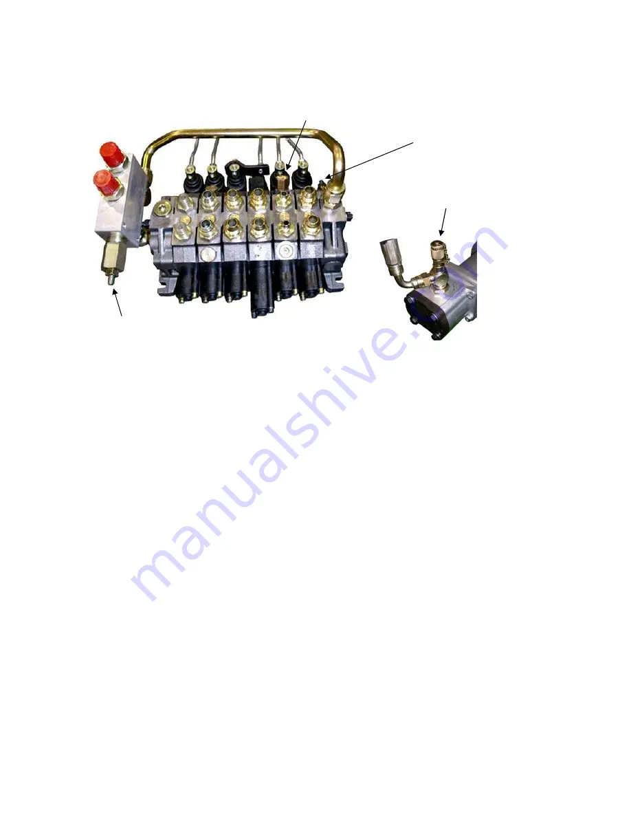
The hydraulic system has three pressure settings which have to be set as follows: 

(2) 

MAIN SYSTEM RELIEF  

PRESSURE TEST POINT 

(1) 

OVERCENTRE VALVE 

(3) 

LIFT PRESSURE 

Before any testing is carried out run the engine and hydraulic system to warm the hydraulic oil to 80°C  176°F  ). 
 
All pressure setting are performed with the engine running at full speed (3600 rpm)
 
OVER CENTRE VALVE 
 

Connect an accurate pressure gauge with a range 0-300 bar ( 0-4300 PSI ) to the test point. 


The pressure should be set at: 

32 bar (460 PSI) for Series 5 machine 


41 bar (600 PSI) for Series 6 machine 


NOTE: If adjustment is required slacken off the lock nut and using a 5mm hex key wind in the screw to 
increase  the  pressure  or  back  off  the  screw  to  reduce  the  pressure.  Retighten  the  lock  nut  when 
adjustments are complete. 
 

(2) 

MAIN SYSTEM RELIEF PRESSURE 


Connect an accurate pressure gauge with a range 0-300 bar ( 0-4300 PSI ) to the test point. 


Check the pressure while pulling the tilt control lever at the end of the rams stroke. 

The pressure should be set at 203 bar (2950 PSI) . 
 
NOTE: 
If adjustment is necessary slacken off the lock nut and wind in the screw to increase the pressure 
or back off the screw to reduce the pressure. Retighten the lock nut when       adjustments are complete. 
 

LIFT PRESSURE 
 

Connect an accurate pressure gauge with a range 0-300 bar ( 0-4300 PSI ) to the test point. 


Check the pressure while pulling the boom control lever at the end of the rams stroke  

(boom  fully 

risen). 


The pressure should be set at 165 bar (2400 PSI). 


NOTE: If adjustment is necessary unscrew and remove the cap lock nut and wind in the screw using  a 
screw driver to increase the pressure or back off the screw to reduce the pressure. Refit  

and  tighten 

the lock nut when adjustments are complete. 

Summary of Contents for 5 Series

Page 1: ...NUAL Page 1 OPERATORS MANUAL Patents Pending US 6397967 438218 10 096997 AU 65424 99 UK 2345046 AU Registered Design 138603 JADEN KANGA GROUP Ph 61 7 5593 4567 Fax 61 7 5593 4398 Email kanga jaden com PO Box 54 Burleigh Heads QLD 4220 Australia ...

Page 2: ...o me for the loader and attachments and have been provided a copy of these procedures for reference and use 3 Have received a copy and understand the Operators Manual and safety information contained therein for all equipment and attachments supplied 4 Understand that I am required to perform a risk assessment JSEA covering all tasks before I operate this machine and or any attachment 5 Understand...

Page 3: ...0 AUSTRALIA or if purchased in the USA KANGA LOADERS USA 3326 HIGHWAY 51 FORT MILL SC 29715 USA Owner Phone Address Mobile Town City Fax Country Post Code Delivery Date KANGA Serial No Email Dealer I The Purchaser have read and fully understand the operator s manual safety instructions and warranty conditions Warranty will only be accepted if this Certificate is completed and returned to KANGA LOA...

Page 4: ...ensioned 100 ftlb 6 Engine Manual Honda Warranty Form 7 is the track slot forward and Tyre Direction correct 8 is the Tyre Pressure to specification Fluid Compartment Check x 9 Radiator Core Hoses and Fittings 1 Battery Electrolyte Level 10 Air Element and hose clearance and Connections tight 2 Engine Oil Level 11 Sediment in Fuel filter tank drain fuel tank 3 Hydraulic Oil Level 12 Drive chain te...

Page 5: ...ty Precautions and Risk Management standards together with the correct operation and attention to maintenance procedures are necessary to ensure a long safe and trouble free working life for your KANGA Loader Some illustrations in this publication show details or attachments that may be different from your machine Guards and covers may have been removed for illustrative purposes however the machin...

Page 6: ...ANKING CHART 18 SAFETY Rules for Attachments 20 operating instructions 24 OPERATING INSTRUCTIONS 24 SERIAL NUMBER REGISTRATION 28 maintenance 29 DAILY OPERATOR MAINTENANCE 29 OPERATOR MAINTENANCE SAFETY CHECKS 30 SERVICE CHART 31 SERVICE TASKS 32 SERVICE TASKS Hydraulics 33 SERVICE TASKS Grease Nipple 35 SERVICE TASKS Tyre Pressure 36 SERVICE TASKS Battery 36 SERVICE TASKS Drive Chain 37 SERVICE T...

Page 7: ...HYDRAULIC ATTACHMENT CONNECTIONS 55 4 IN A BUCKET 56 ROTARY HOE TILLER 57 STANDARD AUGER POWER HEAD 58 HIGH TORQUE AUGER POWER HEAD 59 POWER HEAD OPERATING INSTRUCTIONS 61 STANDARD TRENCHER 62 HEAVY DUTY KC TRENCHER 63 KC TRENCHER CRUMBER BAR 65 TRENCHER OPERATING INSTRUCTIONS 66 BUCKET BROOM 67 warranty 68 WARRANTY 1 YEAR OR 1000 HOURS 68 SPARE PARTS WARRANTY 6 MONTHS 69 specifications 70 SPECIFI...

Page 8: ...or do not understand the process for use of the JSEA chart stop the job and consult a qualified Occupational Health and Safety consultant This symbol has been used throughout this manual to highlight important safety information Ensure you read and understand the information before embarking on any related task This Symbol has been used throughout this manual to highlight critical safety informati...

Page 9: ...a Group Pty Ltd 43 Alex Fisher Drive Burleigh Gardens Industrial Park Gold Coast Queensland 4220 Australia Spares Mechanical Support Phone Aus 1300 4 KANGA 1300 4 52642 Int 61 7 5593 4567 Fax Aus 07 5546 7922 Int 61 7 5546 7922 Email australia kanga loader com Operating Tips Support Phone Aus 1300 4 KANGA 1300 4 52642 Int 61 7 5546 7922 Visit our website www kanga loader com Safety Risk Management...

Page 10: ...amage 2 Visually inspect all components to assure their security of attachment 3 Inspect all areas for evidence of hydraulic oil engine oil or fuel leakage 4 Inspect boom arm assembly area for security of components and sufficient lubrication Check hydraulic cylinders for oil leakage and visible damage 5 Check hydraulic oil lines for correct connection and for signs of leakage 6 Check wheel and ty...

Page 11: ...his operation only Loading unloading should be conducted at very slow speed essentially creeping Use appropriately rated slings shackles and attach to the lifting point on the top of the machine when lifting the machine Always use the tie down points on each side of the machine to secure the Loader when transporting Always use witches hats signage and traffic signals to control the unloading loadi...

Page 12: ...bility of the Loader and may also damage the drive of your machine Come to a complete stop before operating other hydraulic controls Reverse down slopes at slow speed when carrying loads Ensure the machine is fully stopped and turned off before alighting or exiting the machine Never use control levers as hand holds instead utilize the handholds using the thumbs to operate the control levers Travel...

Page 13: ...erk the control levers Always use a steady even action to achieve proper control Touch exhaust hydraulic pipes and fittings drive chains or guards Park or leave Loader unattended on a slope Remove safety decals Remove safety guarding Use mobile telephones or portable radios Operate machine for extended periods at full throttle CAUTION Always exercise care when operating on slopes The Kanga Loader ...

Page 14: ...Jaden Kanga Group Page Jaden Kanga OPERATORS MANUAL 14 SAFETY Summary ...

Page 15: ... or telephone 1100 otherwise consult with your local environment department If underground services are present you must comply with the No Go Zones If the worksite contains or is suspected to contain ANY underground services before any work commences you must follow the relevant No Go Zone safety procedures No Go Zone safety procedures are available from all gas water telecommunications and elect...

Page 16: ... Identify any hazards using the Job Safety and Environmental Analysis Worksheet JSEA o Identify and isolate damaging energies o Check above and below for potential hazards o Determine exclusion zone and delineate with witches hats Assess the Risks o Could a serious injury of accident be avoided o What equipment systems could be damaged o What is the likelihood and consequence o What needs to happe...

Page 17: ...Jaden Kanga Group Jaden Kanga OPERATORS MANUAL Page 17 TASK PLANNING FOR THE KANGA LOADER ...

Page 18: ...L Y CONSEQUENCES Severity Personal injury Extreme Fatality 25 24 22 19 15 Severe Permanent injury or health issue e g loss of limb 23 21 18 14 10 Serious Lose time from work or major treatment by doctor hospital 20 17 13 9 6 Significant Minor treatment injury by doctor 16 12 8 5 3 Minor Near miss of minor potential consequence or first aid injury 11 7 4 2 1 Risk Ranking Matrix Action Required High...

Page 19: ...Jaden Kanga Group Jaden Kanga OPERATORS MANUAL Page 19 ...

Page 20: ...attachments are to be used on this machine No other attachment is to be used on this machine unless the design and use of the attachments has been assessed and authorised by Jaden Kanga and has been supported by a compliant Risk Assessment which has been verified and validated by Safety and Forensic Engineering Pty Limited ...

Page 21: ...TY RULES Always o Establish and maintain a minimum 4 metre 12 foot exclusion zone around the local working area and ensure no person enters this zone other than the operator whilst the machine s engine is running o Keep the general working area clear of bystanders and other workers Loader operations typically rely on rapid movement and direction changes It is important therefore that the whole ope...

Page 22: ... other personnel and operators maintain vigilance about their immediate surroundings o Check with Local Authorities and Land Owners about the presence of underground services within the prospective working area prior to commencement of work and dial 1100 to establish underground services before work commences Never o Place any article or body part between the jaws of an open bucket or under the bu...

Page 23: ...ent of work and dial 1100 to establish underground services before work commences Never o Place any article or body part under the auger at any time ROTARY HOE TILLER SAFETY RULES Always o Establish and maintain a minumum 4 metre 12 foot exclusion zone around the local working area and ensure no person enters the zone other than the operator whilst the machine s engine is running Never o Place any...

Page 24: ...al position from the down position 1 If this lever is not in neutral the engine will attempt to start under full load This will stall the starter motor potentially flattening the battery STARTING Check that the fuel valve where fitted is open Refer to the engine manual for correct throttle 9 starting positions in warm and cold conditions Turn starter key switch 3 to start engine CAUTION Do not mov...

Page 25: ...angle experienced when loading unloading it is recommended to walk behind the loader rather than operate it from the usual driving platform This removes the counter weight effect weight of the driver experienced and greatly improves stability and safety on a steep ramp where sudden angle changes occur All loading unloading to be carried out at a slow speed with due care for personal safety and dam...

Page 26: ...rn to be chosen to suit the situation CAUTION First time users to use slow 1 3 throttle to practice safe operation before commencing work the recommended normal operating speed of the machine is between 2 3 and throttle CAUTION Always ensure that the attachment locking pins are fully engaged at all times CAUTION The Kanga Loader is not fitted with a seat belt The standing position is a safety feat...

Page 27: ...and promotes an efficient tear out When transporting material in the bucket on slopes or rough ground always keep the bucket close to ground level This lowers the centre of gravity of the loader and maximises stability When scraping levelling and surface stripping lower the bucket to the ground tilt it down and so raise the front wheels slightly off the ground Drive forward using the back wheels t...

Page 28: ... Group Page Jaden Kanga OPERATORS MANUAL 28 SERIAL NUMBER REGISTRATION MAIN COMPONENT SERIAL NUMBERS KANGA Serial No Engine Type Serial No Wheel Motors Lift Ram Tilt Ram Hydraulic Pump Control Valve Date Purchased ...

Page 29: ...form mechanical maintenance they should be thoroughly familiar with the unit since their own safety is involved Many costly maintenance jobs can be prevented through observance of the following operator maintenance inspections and checks by KANGA Loader operators Defective components and or equipment malfunctions jeopardise the safety of the operator and other personnel and can cause extensive dam...

Page 30: ...Battery Terminals tight Free of corrosion Adequate battery fluid level Decals Legible All in place Engine Adequate crankcase oil level Fuel No Leakage Adequate fuel level Operating Manual Present with machine ATTACHMENTS ATTACHMENTS Guarding Adequate condition Secure Hydraulics Good condition of hoses inc leaks Good condition of casings inc leaks Good condition of rams inc leaks Controls Correct o...

Page 31: ...X X X X X 220 R R R R X R X X R X X X X X X 120 R R R X X X X X X 20 R R R X X X X ACTIVITY ENGINE OIL ENGINE OIL FILTER AIR FILTER FUEL FILTER IDLE SPEED SPARK PLUGS PETROL VALVE CLEARANCE PETROL VALVE CLEARANCE DIESEL HYDRAULICS HYDRAULIC FILTER HYDRAULIC FLUID GREASE TYRES VISUAL CHECK BATTERY CHAIN TENSIONER PIVOT PINS SERVICE STAMP DATE SERVICED Warranty is on the equipment is subject to the ...

Page 32: ...ery 200 hours of operation See Engine Manual for details Air Filter Service the air filter every 8 hours of operation Replace the filter element every 100 hours See Engine Manual for details Fuel Filter Replace the fuel filter every Service or 100 hours See Engine Manual for details Idle Speed Check engine idle speed every 200 hours of operation Adjust if out of specification See Engine Manual for...

Page 33: ...ydraulic hoses tubes fittings valves and rams for leaks and damage Tighten loose fittings and replace damaged components Check all three pressure settings see procedure on opposite page Adjust if necessary Hydraulic Filters Replace the pressure filter every 500 operating hours and the return line filter cartridge every 200 operating hours Pressure Filter Element Part No 16420 Return Filter Element...

Page 34: ...ssure Retighten the lock nut when adjustments are complete 2 MAIN SYSTEM RELIEF PRESSURE Connect an accurate pressure gauge with a range 0 300 bar 0 4300 PSI to the test point Check the pressure while pulling the tilt control lever at the end of the rams stroke The pressure should be set at 203 bar 2950 PSI NOTE If adjustment is necessary slacken off the lock nut and wind in the screw to increase ...

Page 35: ...draulic Oil ISO 68 Grease Grease daily and inspect for wear all linkage pins every 100 operating hours Grease type Castrol APX T or equivalent The frequency for regreasing depends on the workload and the severity of the working conditions Regreasing during the day of operation may be necessary see Daily Checks OIL DRAIN Series 5 Series 6 7 Grease Nipples ...

Page 36: ...oose bolts replace if worn or damaged Battery Wear safety glasses when checking battery electrolyte Check battery electrolyte and connections every 100 operating hours Top up with distilled water if necessary tighten loose cable connections KANGA Loader Tyre Pressures kPa PSI Lug 18 18 x 8 5 x 8 150 22 Turf 18 18 x 8 5 x 8 150 22 Lug 19 19 x 8 x 10 260 38 Turf 20 20 x 8 x 10 150 22 Turf 20 wide 20...

Page 37: ... nt is possible anymore replace the chain tensioning blocks NOTE Secure bolts 2 with Loctite Lubricate chain with grease To get to the drive chain the loader has to be isolated chocked jacked up on one side supported two wheels and the chain guard have to be removed first SERVICE TASKS Pivot Pins Bottom Pivot Pins Replace the four pivot pins on the attachment plate every 1000 operating hours Part ...

Page 38: ...tioning hydraulic pump Repair or replace hydraulic pump as necessary Worn control valve spool Check pressure delivery from control valve Contact Service Agent Lift control valve relief set too low allowing oil to return to reservoir Adjust relief valve to proper setting Contact service Agent Excessive oil leak past lift cylinder piston seal Repair or replace cylinder as necessary Boom will not low...

Page 39: ...ises and lowers erratically Lift control valve relief set too low allowing oil to return to reservoir Adjust relief valve to proper setting Hydraulic system oil low Check oil and replenish as necessary Oil level should not change Leaks may be present Damaged or blocked line Remove line and remove any obstructions or replace line as necessary Malfunctioning pump Repair or replace hydraulic pump as ...

Page 40: ... any obstructions or replace line as necessary Binding drive motor s Repair or replace motor s as necessary Loose drive chain s Check chain tensioner adjust or repair as necessary Relief valve setting Adjust relief valve Hydraulic Pump TROUBLE PROBABLE CAUSE REMEDY Flow from hydraulic pump erratic or non existent Hydraulic system oil low Check oil and replenish as necessary Oil level should not ch...

Page 41: ...ntrol rod or lever broken or disconnected Repair or replace control rod or lever Engine TROUBLE PROBABLE CAUSE REMEDY Engine will not crank over Low battery output Recharge or replace battery Loose disconnected or broken battery cables Inspect cable s and tighten all connections Repair or replace cables as necessary Faulty Starter Repair or replace starter Faulty circuit wiring Check wiring contin...

Page 42: ... Loader is capable of negotiating very steep inclines outside the safe operating limit of the machine It is possible to tip the loader backwards when climbing a steep bank and with little load in the bucket Do not use this machine on slopes without assessing the risks and fully identifying the required risk control measures by use of a Job Safety and Environment Analysis JSEA or Risk Assessment RA...

Page 43: ...at a minimum of 1 500 kilograms 2 Place packing beneath machine to support machine in the event of jack failure 3 Stand up tracks with both wheels inside it next to loader Fig 1 Note Fit tracks with correct rotation as shown in Fig 1 do not reverse rotation 4 Use Track Fitting tool to spread the two wheels apart until the distance between wheel centres matches the axle distance of the machine Rota...

Page 44: ... Chain Series 5 17600 8 Wheel Nuts 14300 Chain Join Link 17700 9 Tube Lug Tyre 14010 Chain Half Link 17800 Tube 20 Turf 14230 3 Chain Tensioner Frame 12610 10 Lug Tyre 19 14110 4 Chain Tensioner Block 12620 Lug Tyre 23 14206 5 Drive Hub Series 5 12701 11 Turf Tyre 20 14220 Drive Hub Series 6 7 4x 12704 Turf Tyre 20 wide 14171 6 Idler Hub Series 5 12801 Turf Tyre 23 14106 Wheel Bearing Inner 13200 ...

Page 45: ...Jaden Kanga Group Jaden Kanga OPERATORS MANUAL Page 45 MAIN FRAME ARM 5 6 7 SERIES ASSEMBLY DRAWINGS Main Frame Arm 5 6 7 SERIES ...

Page 46: ...2 Tilt Cylinder 10190 16 Drain Plug 13500 Tilt Cylinder Seal Kit 10231 17 Dip Stick 13600 3 Handle Grips 10300 18 Chain Guard R H 13700 4 Lift Cylinder 10390 19 Chain Guard L H 13710 Lift Cylinder Seal Kit 10470 20 Fuel Tank L H 20113 5 Pin A inc nipple washer nut 10700 21 Fuel Tank R H 20114 6 Pin B inc nipple washer nut 10800 Fuel Line Guard pair 20117 7 Pin C inc nipple washer nut 10900 22 Fuel...

Page 47: ...Jaden Kanga Group Jaden Kanga OPERATORS MANUAL Page 47 ENGINE HYDRAULICS 5 SERIES ASSEMBLY DRAWINGS Petrol Engine Hydraulics Diesel Engine ...

Page 48: ...hp 15900 34 Air Cleaner 20663 Honda Engine 24hp 16050 Air Cleaner Element 20680 11 Oil Filter 20hp 24hp 15910 35 Air Cleaner Bracket 20665 12 Fuel Filter 15942 36 Air Cleaner Hose Petrol 20320 13 Throttle Cable 19030 Air Cleaner Hose Diesel 20290 Throttle Assembly 19029 37 Hose Clamp 20350 14 Key Switch 15743 38 Guard Air Cleaner 20140 15 Hydraulic Return Filter Head 16300 39 Engine Mount L H Seri...

Page 49: ...H Wheel Motor 5 8 tube 3 4 JIC Nut 3 4 JIC Nut 10040 11S Valve Bank Section 5 to R H Wheel Motor 5 8 tube 3 4 JIC Nut 3 4 JIC Nut 10040 12S Valve Bank Section 5 to R H Wheel Motor 5 8 tube 3 4 JIC Nut 3 4 JIC Nut 10010 13F Valve Bank Section 6 to Tilt Cylinder rod end 3 8 2180 86 9 16 JIC Fem Straight Sw iv 9 16 JIC Fem Straight Sw iv 10010 14F Valve Bank Section 6 to Tilt Cylinder rear end 3 8 19...

Page 50: ...Jaden Kanga Group Page Jaden Kanga OPERATORS MANUAL 50 HYDRAULIC CONNECTIONS Series 6 ...

Page 51: ...Jaden Kanga Group Jaden Kanga OPERATORS MANUAL Page 51 HYDRAULIC CONNECTIONS Series 7 ...

Page 52: ...Group Page Jaden Kanga OPERATORS MANUAL 52 DECALS Part No Part No 18547 18560 18548 18480 18549 18594 18410 18563 18430 18562 18450 18579 18460 18572 18550 18549 1 18569 18549 1 18571 18541 18500 18546 18490 18568 ...

Page 53: ...Jaden Kanga Group Jaden Kanga OPERATORS MANUAL Page 53 Part No Part No 18594 18565 18557 18567 18558 18541 18559 18557 18564 ...

Page 54: ...HE PART S REQUIRED 7 REFER TO PARTS LISTS 8 INCLUDE THE FOLLOWING ON YOUR FACSIMILE Loader Model Serial Number Engine Type Part Number required Description INCLUDE METHOD OF PAYMENT CONTACT NUMBER DELIVERY ADDRESS TELEPHONE AUSTRALIA 61 7 5593 4567 POSTAL ADDRESS JADEN KANGA GROUP PO BOX 54 BURLEIGH HEADS QLD 4220 AUSTRALIA INCLUDE THE FOLLOWING INFORMATION Loader Model and Serial Number Engine Ty...

Page 55: ...tion is used for all kinds of different attachments and it is controlled by the AUX lever on the control panel Left Side This connection is used for the 4 in 1 bucket and the Angle Blade It is controlled by the 4 in 1 lever on the control panel LOADER WITH TRENCH VALVE This machine has an additional hose connection to connect a trencher The trencher is connected to A and C Other attachments are co...

Page 56: ...Bucket compl UNI att 7 60601 Bush 60021 Hydr Adapter Kit 8 60500 Tee block 61003 Hydr Hose Kit 9 17510 Hose clamp retaining plate 61011 Bolt Kit 10 22000 U Bute bracket 1 19601 Bucket Strip toothed 11 19900 Quick Release Coupling male 2 19611 Bucket Strip straight 12 19910 Quick Release Coupling female 3 19612 Bucket Strip rear 13 19920 Dust Cover male 4 62205 Hydr Cylinder 14 19930 Dust Cover fem...

Page 57: ... FEMALE 14 80500 1 2 x 1 1 2 UNF BOLT NUT 3 19920 FEMALE DUST COVER 15 80600 1 2 SPRING WASHER 4 19930 MALE DUST COVER 16 80700 12 X 8 KEY STEEL 5 22000 U BEAUT BRACKET 17 80800 19 TOOTH SPROCKET 6 80000 BODY 18 80900 13 TOOTH SPROCKET 7 80010 HYDRAULIC HOSE KIT 19 81000 DRIVE CHAIN 8 80100 SHAFT 20 81100 CHAIN COVER 9 80200 BEARING ASSEMBLY 21 81700 HYDRAULIC MOTOR 10 80210 BEARING 30410 HYDRAULI...

Page 58: ...RE DRIVE 8 30100 DRIVE HUB 9 30400 HOSE KIT 10 30410 HYD ADAPTER KIT 11 30110 BOLT KIT 12 32100 PILOT AUGER 13 32130 TUNGSTEN PILOT 14 32010 TUNGSTEN T00TH AUGER TYPES AVAILABLE PART No DESCRIPTION 31020 150mm S C T C 31120 200mm S C T C 31320 250mm S C T C 31430 300mm D C T C 31530 350mm D C T C 31570 450mm D C T C 31590 600mm D C T C 31600 750mm D C T C AUGERS T C TUNGSTEN CARBIDE S C SINGLE CUT...

Page 59: ...HOSE KIT 7 30410 ADAPTOR KIT 8 30120 BOLT KIT NOT SHOWN 9 32100 PILOT AUGER 10 32130 3 TUNGSTEN PILOT 11 32000 CUTTING TOOTH 12 32010 TUNGSTEN DIRT TEETH AUGER TYPES AVAILABLE PART No DESCRIPTION 31020 150 mm S C T C 31120 200 mm S C T C 31320 250 mm S C T C 31430 300 mm D C T C 31530 350 mm D C T C 31570 450 mm D C T C 31590 600 mm D C T C PILOT EXT 31600 750 mm D C T C PILOT EXT AUGERS T C TUNGS...

Page 60: ... Gear 1 PDX 13 Filler Plugs 1 PDX 25 O Rings 2 PDX 14 1 2 x 1 1 3 UNC ht Bolt Spring washer 2 PDX 26 Carrier 1 PDX 15 Hose 2 2m 87 Long 1 Pair PDX 27 Input Pinion 1 PDX 16 7 8 UNO x 3 4 JIC Male Male Nipple 2 PDX 28 Input Adaptor 1 PDX 17 Tapered Thrust Bearing 2 PDX 32 Locking Key 1 PDX 18 Output Housing 1 PDX 33 Gear Oil 450 ml PDX 19 Output Shaft 51mm SQ 1 PDX 34 Spacer Ring 1 PDX 20 Oil Seal 1...

Page 61: ...ed OPERATING INSTRUCTIONS Inspect the cutting tips and teeth Ensure that they are in good condition and firmly attached Note Teeth should display slight movement Check that all bolts are tight Start the auger turning in a clockwise direction by activating the AUX lever downwards Lower the auger by pushing the ARM lever forward If the ground is hard the front wheels of the Kanga Loader will lift of...

Page 62: ...E BOOM 40201 5 TRENCHER SHAFT 40421 22 SPRING 40500 6 DRIVE SPROCKET 5 BOLT 40400 23 BISALLOY WEAR STRIP TOP 40211 7 LABYRINTH SEAL 41215 24 BISALLOY WEAR STRIP BOTTOM 40222 8 BEARING HOUSING 41201 25 IDLER AXLE 40340 9 BEARING 41211 26 IDLER SPROCKET 40330 10 FLIGHT AUGER 40601 27 BEARING 40310 FLIGHT AUGER EXTENSION 40602 28 CIRCLIP 40320 11 QUICK RELEASE COUPLER MALE 19900 29 TRENCHER CHAIN COM...

Page 63: ... NOSE ROLLER BEARING 1 JT 5058 NOSE ROLLER CIRCLIP 1 JT 5060 NOSE ROLLER WASHER TO SQ 2 JT 5062 LARGE NOSE ROLLER COMPLETE 1 JT 5066 DANGER BAR COMPLETE 1 JT 5073 DANGER BAR REAR MOUNTING PLATE TO BACKING PLATE 1 JT 5121 LEFT HAND AUGER COMPLETE 1 22000 JT5011 JT5205 JT5204 JT5016 JT5181 JT5182 JT5184 JT5180 JT5165 JT5204 JT5205 JT5056 JT5055 JT5057 JT5054 JT5058 NOSE ROLLER COMPL JT5185 JT5146 JT...

Page 64: ...T 5182 SPROCKET RETAINING WASHER TO SHAFT ZC BOLT WASHER 1 JT 5184 SEAL PROTECTOR 1 JT 5185 ADJUSTING SCREW COMPLETE BOOM 1 JT 5187 NUT TO ADJUSTING SCREW 2 JT 5188 NUT TO ADJUSTING SCREW 1 JT 5189 RUBBER FLAP TOP 1 JT 5191 GUARD 1 JT 192 REAR OF GUARD TO SIDE SHIFT PLATE BOLT FLAT WASHER NUT 4 JT 195 REAR OF GUARD TO SIDE SHIFT PLATE RUBBER WASHER 4 JT 5200 SPANNER 1 JT 5202 SPANNER TO OUTER BOOM...

Page 65: ...G BUSH 1 KCB 171 FOLD BACK SCRAPER RETAINING PIN LONG 1 KCB 172 FOLD BACK SCRAPER REAR PIN 1 KCB 173 FOLD BACK SCRAPER RETAINING PIN SHORT 1 KCB 174 FOLD BACK SCRAPER SPRING 1 KCB 175 FOLD BACK SCRAPER SHOE 140 mm 1 KCB 176 FOLD BACK SCRAPER SHOE 190 mm 1 KCB 177 FOLD BACK SCRAPER SHOE 240 mm 1 KCB 178 FOLD BACK SCRAPER SHOE 290 mm 1 KCB 180 FOLD BACK SCRAPER PIN SPACER WASHER FLAT WASHER ZC 8 KCB...

Page 66: ...correct tension and should be adjust as required This is achieved by loosening the 16mm bolt adjusting the wedge and retightening the bolt OPERATING INSTRUCTIONS Position the trencher activate the AUX lever so that the chain runs along the top of the boom and returns back towards you on the underside Pressurise the TILT ram so that the boom and chain arcs down to dig a trench When the desired dept...

Page 67: ...ELEASE COUPLING FEMALE 16 51700 BROOM BRUSH 4 19920 FEMALE DUST COVER 17 52400 DRIVE CHAIN 5 19930 MALE DUST COVER 18 53300 INSERTION RUBBER 6 22000 U BEAUT BRACKET 19 53400 BACKING STRIP 7 FRAME 20 52600 MOTOR MF14 8 50200 CHAIN GUARD COVER 21 54100 HOOK CHAIN 9 50300 SHAFT 30410 HYDRAULIC ADAPTOR KIT 10 50101 SHAFT SPACER 80010 HYDRAULIC HOSE KIT 11 50700 SPROCKET HYDRAULIC MOTOR 51100 BOLT KIT ...

Page 68: ...ays of purchase Service Warranty service must be carried out by an authorized Kanga Dealer For contact details contact Kanga Loaders on 07 5546 6399 Battery Warranty Pro rata One to three months Free replacement Four to twelve months Pro rata over 12 months Exclusions No Warranty Normal maintenance servicing and replacement items such as spark plugs oil oil filters air filter muffler tires cutting...

Page 69: ... defective within the conditions of normal usage Breakage or damage to any part caused by abuse or misuse will not be considered Hydraulic hoses will not be covered by warranty if any signs of external damage are apparent Tyres tubes and tracks are not covered by warranty The warranty period is for six 6 months from the delivery date and applies to only genuine spare parts This warranty does not c...

Page 70: ...cu in rev 11 3 cc rev 0 690 cu in rev Pump output 38 l min 10 0 gUS min 40 l min 10 6 gUS min 40 l min 10 6 gUS min System pressure 203 bar 2950 psi Hyd reservoir capacity 55 l 14 5 gUS min BUCKETS Standard bucket capacity 0 1 m3 3 5 cu ft 4 in 1 bucket capacity 0 1 m3 3 5 cu ft STANDARD EQUIPMENT Auxilary safety shut down Enclosed drive chains Self levelling bucket Greasable linkage pins Auxiliar...

Page 71: ...t to hinge pin 1730 68 C Overall height 1260 50 D Overall length 2070 81 E Overall wheel width 980 39 B Dump height 4 in 1 bucket 1730 68 F Bucket max reach at 45 560 22 G Dump height std bucket 45 1075 42 H Angle of departure I Max roll back J Bucket width 1050 41 K Overall length less bucket 1620 64 L Ground clearance 125 5 27 47 ...

Page 72: ... 3 cc rev 0 690 cu in rev Pump output 40 l min 10 6 gUS min System pressure 203 bar 2950 psi Hyd reservoir capacity 55 l 14 5 gUS min BUCKETS Standard bucket capacity 0 1 m3 3 5 cu ft 4 in 1 bucket capacity 0 1 m3 3 5 cu ft STANDARD EQUIPMENT Auxilary safety shut down Enclosed drive chains Self levelling bucket Greasable linkage pins Auxiliary hydraulics Non slip rear step Universal attachment pla...

Page 73: ...to hinge pin 1780 70 C Overall height 1310 52 D Overall length 2070 81 E Overall wheel width 1015 40 B Dump height 4 in 1 bucket 1780 70 F Bucket max reach at 45 560 22 G Dump height std bucket 45 1125 44 H Angle of departure I Max roll back J Bucket width 1050 41 K Overall length less bucket 1620 64 L Ground clearance 170 6 75 37 47 ...

Page 74: ...cc rev 0 690 cu in rev Pump output 40 l min 10 6 gUS min System pressure 203 bar 2950 psi Hyd reservoir capacity 55 l 14 5 gUS min BUCKETS Standard bucket capacity 0 1 m3 3 5 cu ft 4 in 1 bucket capacity 0 1 m3 3 5 cu ft STANDARD EQUIPMENT Tracks Service warning indicator Auxilary safety shut down Enclosed drive chains Self levelling bucket Greasable linkage pins Auxiliary hydraulics Non slip rear...

Page 75: ... to hinge pin 1795 71 C Overall height 1325 52 D Overall length 2070 81 E Overall wheel width 1040 41 B Dump height 4 in 1 bucket 1795 71 F Bucket max reach at 45 560 22 G Dump height std bucket 45 1140 45 H Angle of departure I Max roll back J Bucket width 1050 41 K Overall length less bucket 1620 64 L Ground clearance 188 7 5 38 47 ...

Page 76: ...engaged in the task or others in the vicinity 3 Document the Control Measures For each identified hazard assess the associated level of risk to those involved and then list the control measures required to eliminate or minimise those risks 4 Identify Who is Responsible Document the name of the person responsible for implementing the control measure 5 Monitor and Review Make sure the activity is su...

Page 77: ...Jaden Kanga Group Jaden Kanga OPERATORS MANUAL Page 77 ...

Page 78: ...Jaden Kanga Group Page Jaden Kanga OPERATORS MANUAL 78 5 5 ...

Reviews: