background image


SW-VDYWA LL


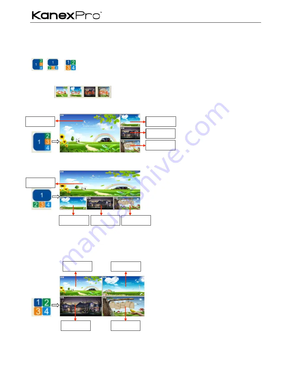
5.4.5  Picture outside Picture (POP) Displaying 

Function: To show the output images of different channels on a single screen. It means that while the screen is showing the frame of 
the main video, any of the other three input images (Had been compressed) also can be showed on this screen, but locate beside 
the main image. That makes users be able to monitor the other input images. In one word, it means that the other three images are 
just beside the main image. 
Detailed operations: While the software is running normally, click on the button 

, or

, the display mode area on the software interface will show the display effect of all the four input channels. 

The images (all are complete) on any output channels are made by the four input images. 


The buttons 

  are used for checking the output image of any one channel.   

The effects are showed in 

Figure 5-12

 to 

5-14


Figure 5-12 The First POP Display Effect 


Figure 5-13 The Second POP Display Effect 


Figure 5-14 The Third POP Display Effect 


Button 

From input 

2


From input 

1


From input 

4


From input 

3


Button 

From input 

2


From input 

1


From input 

4


From input 

3


Button 

From input 

2


From input 

1


From input 

4


From input 

3


Summary of Contents for SW-VDYWALL

Page 1: ...SW VDYWALL 1 SW VDYWALL ...

Page 2: ...oduction 9 5 Operations of the Software 11 5 1 Introduction of the Software 11 5 1 1 Installation uninstallation 11 5 1 2 Control connection 11 5 2 Main Interface 12 5 3 Menu Bar Function Settings 12 5 3 1 File Button 12 5 3 2 Connection Button 13 5 3 3 View Button 13 5 3 4 Help Button 13 5 4 Main Function Settings 13 5 4 1 4x Zoom in Function 13 5 4 2 3x Zoom in Function 13 5 4 3 Matrix Switching...

Page 3: ... Diagram of Video Wall Displaying 24 6 2 Diagram of Multi Viewer Displaying 26 6 3 Diagram of Full Images Displaying 27 7 Firmware Upgrade 29 8 Troubleshooting Maintenance 30 9 Safety Operation Guide 30 10 Warranty 31 ...

Page 4: ...of output displays up scaling if needs to be The scaler is also manually adjustable through front panel buttons featuring selectable output settings of up to 1920 x 1200 60Hz Ideal for operation centers military installations shopping malls and airports where demand for high resolution 4x4 video wall is critical 1 2 Package Contents Ø 1 x SW VDYWALL Ø 1 x RS232 cable 1 35m in length Ø 1 x Power Co...

Page 5: ... can control SW VDYWALL with control software SW VDYWALL after setting the right IP address in it 6 AC100V 240V Used for accessing the household current power 3 2 Connection with RS232 Communication Port With the RS232 port the processing switchers can be control by the control software SW VDYWALL This RS232 communication port is a female 9 pin D connector The definition of its pins is as the tabl...

Page 6: ...2 cable to connect the COM port of the computer to the RS232 connector of SW VDYWALL Figure 3 3 Connecting to a PC 2 Run the control software and select RS232 connection 3 If connection is OK then we can control the SW VDYWALL ...

Page 7: ...nning state 3 Menu function panel Choose the functional button required and confirm 4 Input output channels 4 input channels and 4 output channels 5 Function pattern panel Common functions for output image displaying effects 6 Custom panel Used for saving or recovering the customized settings Note 4 5 and 6 are the operation areas for shortcut 1 For the non numeric buttons you can use the menu but...

Page 8: ...he parameter such as channel resolution etc 4 3 Operations of the Input output Selection Buttons Buttons Operation Description Select the corresponding input image from the images of the 4 input channels Select the corresponding output image from the images of the 4 output channels Note 1 While it is in 4x full screen zoom in and 3x zoom in function menu it is unable to set the input or the output...

Page 9: ...levels and save the settings Customized menu button call Shortcut button to clear the customized menu Numeric buttons to set the corresponding shortcut buttons of different menu levels Note In the operational area of the shortcut buttons when you press on any button it will show the detailed information of the present menu on the LCD screen 4 6 Menu Levels Introduction In this part we mainly intro...

Page 10: ... MENU Set Position Position setting MENU Channel 1 1HP 0001 1VP 0001 MENU 1HW 0001 1VW 0001 MENU Adjust windows Fine tuning MENU Channel 1 1HP 1HW MENU 1VP 1VW MENU Overlay MENU OUT 1 CH1 CH2 CH3 CH4 1 2 3 4 MENU Board MENU OUT ALL CH1 CH2 CH3 CH4 OFF OFF OFF OFF MENU Display MENU OUT 1 CH1 CH2 CH3 CH4 ON ON ON ON MENU Color MENU OUT 1 Brightness 0512 Contrast 100 MENU POP Channel Switch Type 1 IN...

Page 11: ...n uninstallation Using the software one can control SW VDYWALL l Installation Copy the software files to the controlling computer and run the executable program SW VDYWALL_v1 1 30 exe showed in Figure 5 1 l Uninstall Delete all the software files Note SW VDYWALL_v1 1 30 exe is only used in its own given path Figure 5 1 SW VDYWALL Control Software SW VDYWALL 5 1 2 Control connection Ways for Softwa...

Page 12: ...onnection and if user wants to change another control way please also disconnect the current connection first 5 2 Main Interface Figure 5 3 shows the main interface and the various setting areas on it The settings mentioned below Section 5 3 to Section 5 6 are referred to it Figure 5 3 Main Interface 5 3 Menu Bar Function Settings 5 3 1 File Button Function To open the saved image display mode fil...

Page 13: ...t is able to set the resolution of any single output by checking the option box full mode and also able to set as a whole resolution But not able when in any one of the other four modes 2 It is not able to set the correspondences between the inputs Channel input switch and the four outputs 3 It is not able to set the overlay hierarchical relationship of a single input channel or to set the hierarc...

Page 14: ...ick on the button the display mode area on the software interface will show the output display mode of any one of the input channels The output images are the same with each other and also the same with the input image Shown in Figure 6 5 5 4 4 Picture in Picture PIP Displaying Function SW VDYWALL is able to present all the input images of the four channels on a single screen It means that while t...

Page 15: ...ffect Figure 5 11 The Fifth PIP Display Effect Button From input 2 From input 1 bottom layer From input 4 From input 3 Button From input 3 second layer From input 2 third layer From input 1 bottom layer From input 4 top layer Button From input 2 From input 1 bottom Layer From input 4 From input 3 Button From input 2 From input 4 From input 3 From input 1 bottom layer ...

Page 16: ...ations While the software is running normally click on the button or the display mode area on the software interface will show the display effect of all the four input channels The images all are complete on any output channels are made by the four input images The buttons are used for checking the output image of any one channel The effects are showed in Figure 5 12 to 5 14 Figure 5 12 The First ...

Page 17: ...l or all channels just select the corresponding radio button and drag the slider on the slider bar to an appropriate position And then press the button Set to confirm In this area the button Reset is used to set the value of contrast brightness to the factory default Default value of image contrast 100 brightness 512 Border Setting When you need to set the border of the image of a single channel o...

Page 18: ...om In Out To zoom in out in both horizontal direction and vertical direction The button HZoomIn and HZoomOut are for adjusting in a horizontal direction And VZoomIn and VZoomOut are for adjusting in a vertical direction Note 1 The image begins to zoom in out from the top left corner and extends to a fixed maximum size whenever you drag the mouse or set the values 2 Image zoom setting is available ...

Page 19: ...confirm Figure 5 18 and Figure 5 19 will show you the difference between the original image and the image adjusted Note 1 Bezel size setting is mainly used when there is offset between the images on the displayers 2 In Figure 5 18 the position of the images on the left side is lower than the right ones The place marked with circle shows the effect that the images joined before after Figure 5 18 Th...

Page 20: ...to change the output resolution respectively In other modes the resolution of all outputs only can be set as a whole Select the check box Full mode to set the resolution of single channel and deselect this check box to set the resolution of all channels as a whole And then press the button Set to confirm The default resolution is 1080P 1920 1080 l Input Channel Setting SW VDYWALL supports to assig...

Page 21: ...wn in Figure 5 23 Figure 5 23 Output Display On Off l Communication Information This area is to check the connecting status between the computer and SW VDYWALL showed in Figure 5 24 and choose a proper connection way to check if it is well connected The detailed information is showed on the right side of the picture Note If the adjusting image does not synchronize with the output images show on th...

Page 22: ...er User can set it in Mode setting press the button Set Name to rename it And there is no limitation to name it Name repetition long name and special characters are available No Description Function Button 1 2 3 4 Default 4x zoom in modes the first one is for outputting the image from input channel 1 and the second one is for channel 2 and so on 5 6 7 8 Default 3x zoom in modes the first one is fo...

Page 23: ...1 Used to save the modified PIP mode same to PIP display mode No 14 No 18 but has been modified with additional function settings 32 33 34 Used to save the modified POP mode same to POP display mode No 19 No 21 but has been modified with additional function settings 5 6 2 Shortcut Button Customization With the shortcut buttons SW VDYWALL can switch quickly to a customized display mode The operatio...

Page 24: ...ll images matrix switching and distribution displaying The system diagrams of the application occasions are showed as below 6 1 Diagram of Video Wall Displaying 4x Zoom in It means SW VDYWALL is able to zoom in the input image and spilt to 4 parts and then full screen display on the output displayers one to one Figure 6 1 Diagram of 4x Zoom in Displaying ...

Page 25: ...utput image on the first output channel the displayer just shows a blue screen and the images on the second third and fourth displayers rotated 90 degrees make up a whole image same as the input image Figure 6 2 Diagram of 3x Zoom in Displaying ...

Page 26: ...lti Viewer Displaying Multi Viewer It means SW VDYWALL is able to display multi channel output images on a single displayer And it supports several displaying effects such as PIP POP etc Figure 6 3 Diagram of Multi Viewer Displaying ...

Page 27: ...VDYWALL 27 6 3 Diagram of Full Images Displaying Matrix switching With four input ports and four output ports SW VDYWALL is able to display any inputs to any outputs Figure 6 4 Diagram of Matrix Switching ...

Page 28: ...SW VDYWALL 28 Distribution display All output images are the same and also the same as the image of one input channel Figure 6 5 Diagram of Distribution Displaying ...

Page 29: ...llowing operations Figure 7 1 The Upgrade Program File When the program is running normally press the button on the main interface showed in Figure 5 3 While it is connected press the button and find the BIN file and then it is ready to upgrade Press the button Updata When all are done it will appear with a window shows the message updata success Press the button OK to confirm and then user can us...

Page 30: ...WER indicator doesn t work or no respond to any operation please make sure the power cord connection is good 6 If the output image is interfered please make sure the system is grounded well 7 If the static becomes stronger when connecting the video cables it probably due to the incorrect grounding please correct it otherwise it would damage the switcher 8 If the switcher cannot be controlled by th...

Page 31: ...ER WARRANTIES To the maximum extent permitted by applicable law KanexPro disclaims all other warranties either express or implied including but not limited to implied warranties of merchantability and fitness for a particular purpose with regard to the product and any related written materials This limited warranty gives customers specific legal rights Customers may have other rights depending on ...

Reviews: