上海标星科技发展有限公司
K&M Technologies Ltd.
• Website
:
www.knmsonic.com
• Email:
[email protected]
• Tel: +86 0512 - 57403727
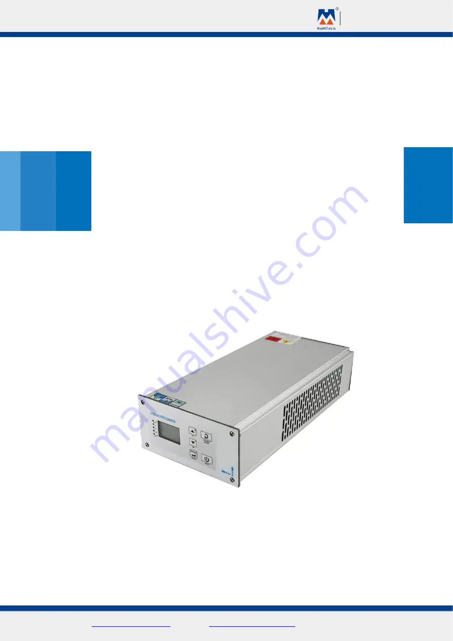
User’s Manual
Model: KM-QD-G
Page 1: ...K M Technologies Ltd Website www knmsonic com Email mfrlucy vip 163 com Tel 86 0512 57403727 User s Manual Model KM QD G...
Page 2: ...rameter setting 21 11 Protection function 22 12 Factory default setting 24 12 1 User s parameter management menu 24 12 2 Factory setting menu 25 12 3 Operation parameter verification menu 26 13 Malfun...
Page 3: ...y must meet the requirement of the related country All the operation parameters can be set by user but the parameters protected by passwords shall be kept at factory default parameters For any support...
Page 4: ...ature sensor cables shall not be too long and shall not be rolled up otherwise the temperature will go up to affect the accuracy Professional personnel shall be in charge of the repair or maintenance...
Page 5: ...ture shall not exceed 40 and moisture shall be exceed 75 Please do not make metal or vapor go into the generator case Long time exposure to the chemicals will damage the electronic elements in the gen...
Page 6: ...K M Technologies Ltd Website www knmsonic com Email mfrlucy vip 163 com Tel 86 0512 57403727...
Page 7: ...K M Technologies Ltd Website www knmsonic com Email mfrlucy vip 163 com Tel 86 0512 57403727...
Page 8: ...dard machine with PLC start mode the port will control the amplitude in stages For programmed machine the port will be used as Emergency Stop input Note4 For standard machine with Press Button start m...
Page 9: ...n The maximum driving current for 24V power supply input is 1A Signal cables shall be screened type with diameter 0 3mm2 length shall not exceed 6meters Analogue quantity Input output port Control mod...
Page 10: ...n insulation convert circuit must be added externally Communication port Attention RS485 communication port shall be insulated and the twisted pair wire shall be screened in strong interference place...
Page 11: ...equency limit 1x7 alarm for malfunction 1x15 exceed power limit 03H function code Reading save register IP type 4x Scope 4x0 4x33 4x0 amplitude mode 4x11 shake off delay 4x1 amplitude stage A 4x12 sha...
Page 12: ...asonic energy double bit 3x2 load resistance value 3x8 ultrasonic period 3x3 amplitude strength value 3x9 quality result 3x4 real time power 3x10 work times double bit 05H function code compulsory sin...
Page 13: ...status OVL overload ERROR malfunction of the system Power Switch in Ultrasonic Generator Increase Note1 number increase or go left or go up decrease Note1 number decrease or go right or go down Enter...
Page 14: ...unt to zero menu will appear Note2 Select the parameter to be adjusted shortly press the Enter key to start the adjustment press it again to exit the adjustment long press on this key will return to p...
Page 15: ...mfrlucy vip 163 com Tel 86 0512 57403727 Step 1 Press Enter key to enter into Factory Setting Press key to input password 2005 Step2 Press downward key to select Mode Type Press the Upward or Downward...
Page 16: ...ress the Upward or Downward key again to choose PLC change Key to PLC press Enter again to confirm and then Search key Step 4 Press the Upward or Downward key to select Setting icon on the display and...
Page 17: ...face 8 1 LCM 12864 LCD display interface 8 11 Start Page After turning on the power machine model rated power rated frequency software version and manufacture date etc will be displayed Attention Some...
Page 18: ...value is the better for ultrasonic weld result b For verification in factory please press and hold the TEST key to start checking the ultrasound and record value of B the first 2 seconds data and the...
Page 19: ...y pressing the Plus Minus key to go into the menu for clearing the count to zero press ENTER key to clear the count to zero and press RESET key to cancel the clearing 9 Function menu Function menu in...
Page 20: ...nnot be started by pressing the start button but external port can be started normally for easy parameter adjustment 10 Parameter setting 10 1 Amplitude setting The ultrasonic work amplitude can be ad...
Page 21: ...or Energy mode ultrasonic energy scope is 0 50000J d For Contact Shut off mode ultrasonic contact shut off time shall be 0 9 99S e Cooling time Cooling after ultrasonic action shall be 0 9 99S It is p...
Page 22: ...asonic start time will be adjustable at 0 9 99S It is prohibited to set at 0 for second time ultrasonic start k Work mode continuous time energy and contact shut off while programmed model has no cont...
Page 23: ...re difficult to start this value can be increased c Energy Stop It is for slow stop of the ultrasonic system It is slower when the value is bigger For the welding horns which have bigger residual osci...
Page 24: ...nic check it will alarm to indicate excessive resistance h Peak voltage it is the protection voltage limits on the two ends of the transducer The value shall be increased properly for frequent protect...
Page 25: ...0512 57403727 a Authority to set select Administer all the operation parameters for operators cannot be set to avoid random change by operators b System Language Chinese and English c Voltage please...
Page 26: ...Factory verification Select Factory Verification to return to main page to do ultrasonic check to see the current amplitude value then prohibit any change after verification b Constant amplitude scope...
Page 27: ...replace plug in devices Wrong parameter configuration Possible causes Wrong parameter setting Systematic data was abnormally initialized when saving Solution Re set the data Over heating Possible caus...
Page 28: ...the permitted scope Welding horn impedance is too big or over loaded Solutions Check the horn start ultrasonic check press TEST to see if the horn is normal Decrease the amplitude value or reduce the...
Page 29: ...ONIC300 XX 15KHZ 20KHZ SONIC4000 XX 15KHZ Frequency VOLTAGE 220V 10 50 60Hz Rated current 2 4A 3 2A 4 8A 6 5A 9 6A 12 9A Rated power 750W 825W 1000W 1100W 1500W 1650W 2000W 2200W 3000W 3300W 4000W 440...
Page 30: ...specified model number which is helpful to choose the related parts For example SONIC2000WA 20 which will be printed on the plate of the generator it means the product SONIC digital ultrasonic genera...
Page 31: ...when multiple generators are installed in one line the distance between each other shall be not less than 5cm When multiple generators are installed vertically the distance between each other shall be...
Page 32: ...the working cycle is more than 10S you can choose continuous mode and set it as Zero Attention The common port COM_OV is connected with Ext Power OV When using 24V power supply the 24V auxiliary power...
Page 33: ...ted When the delay time is set at Zero it is pressure trigger for starting the ultrasonic system The pressure trigger port is connected to the pressure switch In Grounding mode the grounding test port...
Page 34: ...age Frequency searching or reset after malfunction remark 1 Setting button goes to parameter setting Testing button ultrasonic testing Or enter into next page Welding horn adjusting button Ultrasonic...
Page 35: ...ng for adjusting operation parameters See details in Function menu parameter setting Protection function Verification password is 2005 See details in Function menu protection function Counts Quality T...
Page 36: ...time In case of malfunction caused by any following reasons even though it is in warranty period we will provide service with charge 1 Incorrect operation or problems caused by any change or repair w...