Manual: CMOS Industrial Camera LOGLUX
i5
Version 1.08 (04/07)
KAMERA WERK DRESDEN GmbH
Page 41 of 46
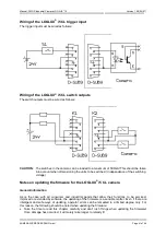
Wiring of the LOGLUX
®
i5 CL trigger input
The trigger input must be wired as follows:
Wiring of the LOGLUX
®
i5 CL switch outputs
The switch outputs must be wired as follows:
CAUTION:
The switches in the camera can be loaded to a maximum of 500mA! This should be taken
into account when dimensioning the units to be switched (in dependence of the switching
voltage).
Notes on updating the firmware for the LOGLUX
®
i5 CL camera
General information
As is the case with all consumer and industrial goods that allow their functions to be serviced,
improved or extended by software, the updating of the firmware is a sensible matter. Even if there are
intelligent and safe ways of updating, operator errors can be remedied to a limited degree only. For
this reason, the following should be noted when updating the firmware:
•
Take the time to read this chapter carefully and don't rush things when updating the firmware!
Once damage has occurred, it will surely take longer to remedy it!

