116
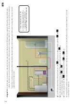
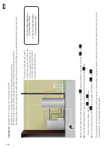
Scheme 04 :
the Hydro insert is connected to a technical w
ater puffer
.
The Hydro insert is turned off when the upper probe is satisfi
ed.
The heating Hydro insert is switched on when the inferior probe is not satisfi
ed.
The heating w
ater will then be tak
en from this puffer by means of the pumps and the non-commanding relay from the Hydro insert’
s control unit.
a)
To set the temper
ature at the top of the puffer
, press the
k
ey
. Use the
and
k
eys to select the desired degrees
b)
To set the temper
ature on the bottom of the puffer
, press the
k
ey and use the
e
and B k
eys to select the desired degrees
c)
To set the work power
, press the
k
ey and adjust it with the
and
ke
ys.
The restart from the stand-by state occurs automatically when the temper
ature detected by the lower puffer probe is lower than the set temper
ature (b)
II
I
The scheme is indicative and w
ants to
demonstr
ate only the components that can
be managed by the Hydro insert.
Any relay
pumps must be controlled separ
ately from
the Hydro insert
I
=
ON / OFF higher thermostat
on
Technical w
ater Puffer
.
II
=
ON / OFF lower thermostat
on
Technical w
ater Puffer
.
EN
Summary of Contents for Cloe 17B
Page 47: ...45 IT Cod 001111 NOTE...
Page 48: ...46 IT Cod 001111 NOTE...
Page 93: ...137 EN NOTES Cod 001111...
Page 94: ...138 EN NOTES Cod 001111...
Page 140: ...92 ES Cod 001111 NOTAS...

