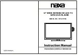
background image


LED Driver 

CB1  470pF/1KVC5.0CT 

DIP 


LED-VCC 

L25 

2

  BD1206 

D15 

SB260,2A,60V 

L26 

LED+ 

LED-VCC 

L22 

150uH/1.5A 

DIP 

BD1206 

RB3 

CB2 

S

OT

2

2

3

-D


CB3 

330K/0805 

CE16 

CE15 


R1 

220uF/50V 

NC/220uF/50V 1000pF/1KV 1206 

100pF/1KVC5.0CT 

Q20 

RB7 

GATE-IN 

RB6 

10R/1206 

SOT223-G 

390K/0805 

NC 

OVP-IN 

RB8 

0R/0402 

S

O

T

2

2

3

-S


RB34 


10K/0402 

CB4 

R2 

RB9 

100pF/0402 

20K/0402 

ISENSE-IN 

RB10 

220R/0402 

1


LED+ 

10 

10 

LED+ 

CN8 

CB5 

RB11 

RB12 

RB13 

RB14 

LED1 


NC 


100pF/0402 

0.36R/1%/1206 

0.36R/1%/1206 

0.36R/1%/1206 

0.36R/1%/1206 

LED2 


SMD-R1206 

SMD-R1206 

SMD-R1206 

SMD-R1206 

LED3 


LED4 


LED+ 

LED+ 

Q21 

LED1 


SOT223-G 

LED2 


ADJ 


LED3 


CN9 


SOT223-

4

SOT223-D 

LED4 


J-B2.0-6P-W 

OUT 


RB35 

0R/0603 

SOT223-S 

LED+ 

IN 

SM1105NSV 

D17 

NC 

CB6 

U18 

B

L


O

N

/O

F

F


1uF/0603 16V 

MP3398AGF-Z/OB3363VP 

+12V SB 

RB16 

4.7R/1206 

GATE-IN 

+12V SB 

15 

VIN 

GATE 

14 

+12V 


CB7 

0.47uF/50V/0603 

16 

VCC 

ISENSE 

13 

ISENSE-IN 

RB17 

RB19 

RB20 

RB21 

ON/OFF 


CB8 

0.47uF/50V/0603 

RB18 

270R/0603 

COMP 

GND 

NC/0805 

NC/0805 

NC/0805 

NC/0805 


VBL_CTRL 

VBL_CTRL 

RB23 

10K/0402 

BL_ON/OFF 

BL_ON/OFF 

EN 

OVP 

12 

OVP-IN 

1


RB25 

CB10 

RB24 

300K/0402 

OSC 

LED1 

11 

LED1 

BL_ON/OFF

RB36 

0R/0402 

10 


ADIM 

LED2 

CB11 

RB27 

BL_PWM 

100K/0402 

100NF/0402 

PWM

E

-PAD


LED3 

100pF/0402 

0R 0402 


ISET 

LED4 

LED2 

I

M

M

I

N

G


17


CB12 

RB29 

RB37 

RB31 

RB32 

CB15 

100pF/0402 

NC/0402 

PWM 

NC/0R 

24K/0402 27K/0402 100pF/0402 

LED3 

BRI_ADJ-PWM0 

BRI_ADJ-PWM0   

RB28 

10K/0402 

BL_PWM 


CB16 

RB33 

100pF/0402 

0R 0402 

RB30 

CB14 

1


LED4 

100K/0402 

1NF/NC 

CB17 
100pF/0402 

A

Size 

Document Number 


Rev 

Custom 

LED Driver 

Date: 

Thursday, November 12, 2015 

Sheet 

of 

Summary of Contents for K-LED32HDXDT2

Page 1: ...3 Alignment Procedure 4 Block diagram 5 Scheme Diagram 6 Troubleshooting K LED32HDXDT2 This manual i sthe latest at themeti of prnting and does not include the modification which may be made after the...

Page 2: ...ghting flash with arrowhead symbol with an equilateral triangle is intended to alert the user to the presence of uninsulated dangerous voltage within the products enclosure that may be of sufficient m...

Page 3: ...r push objects of any kind into this television set through cabinet slots as they may touch dangerous voltage points or short out parts that could result in a fire or electric shock Never spill liquid...

Page 4: ...and supporting structure grounding of the lead in wire to an antenna discharge unit size of grounding conductors location of antenna discharge unit connection to grounding electrode and requirements f...

Page 5: ...Y 21 If you are unable to restore normal operation by following the detailedprocedurein your operating instructions do not attempt any further adjustment Unplug the set and call your dealer or service...

Page 6: ...Alignment Procedure MS306 Series MODEL MS306 MS306B MS306C MS306D MS306G MS306P MS306BP MS306CP MS306DP VERSION V3 0 PREPARED BY DATE 2014 1 24 APPROVED BY DATE...

Page 7: ...at up to 1080p can be supported USB support image audio and video up to H 264 playing The whole process of alignment includes ADC calibration and White Balance adjustments 2 Factory Menu 1 Methods of...

Page 8: ...M reset DO System initialization Restore all OK data except the White Balance and ADC data Only for R D 7 SET FAC CH DO Preset specific factory channels for OK specific factory Press left and right bu...

Page 9: ...Current Current Source TV AV1 AV2 YPbPr HDMI need OK Source adjustment COLOR TEMP NORMAL Medium Cool Ware OK R GAIN 128 R GAIN OK G GAIN 128 G GAIN OK B GAIN 128 B GAIN OK R OFFSET 128 R OFFSET OK G...

Page 10: ...NG 7 HOTEL Hotel submenu not adjust OK MENU SHOP INIT submenu ITEMS Default Description Status Setting Volume 30 0 100 adjustable OK PIC MODE STANDARD Standard Bright Mild User OK SOUND MODE STEREO Mo...

Page 11: ...t Contrast curve Exclusively used by R D OK Curve Saturation Saturation curve Exclusively used by R D OK Curve Hue Curve Hue curve Exclusively used by R D OK Sharpness Sharpness curve Exclusively used...

Page 12: ...menu ITEM Default Description Status Setting Erase HDCP Key Do Only for R D OK Reset HDCP Key Do Only for R D OK UsbHdcpkey Do Only for R D OK Update USBPortNumset 1 USB port number set 1 or 2 OK 5 De...

Page 13: ...tialize the set Note After step 9 Hotel Menu will be disabled by default Therefore if the order requires hotel function it is necessary to enable hotel function by set Design MENU Service Menu HOTEL E...

Page 14: ...nal and generator The pattern of the signal should be used are White Chroma2329 pattern 113 and Grey pattern 114 The format of signal are respectively 720P for HDMI1 Chroma2329 Timing 69 PAL Chroma232...

Page 15: ...d White Balance automatically is out of the range of this file Please refer to the relevant technical file of HuiZhou factory of TCL 6 Chip list of software programming before SMT Following chips must...

Page 16: ...f the OSD choosing the contrast item and press 9 7 3 and 5 in series Factory Menu will appear in the left top of screen 2 Select the USB UPDATE item press left or right key to enter the update box 3 S...

Page 17: ...lly 3 Upgrading method 2 1 Press the MEUN button of Remote Control then select the Software Update U item in Option sub menu press left or right key to enter the update box 2 Press left button Select...

Page 18: ...ely there you go the Design Menu 2 Select the SERVICE MENU item press OK and RIGHT button of the remote to enter submenu 3 Select the PROJECT ID item press OK or RIGHT button of the remote to enter th...

Page 19: ...5A 3 4 SW 1 2 3 3V FOR PANEL IN 5 NC R9 47K 1 EN GND R1 R10 3V3STB 6 FB 15K_1 CE5 C21 5VSTB 2 C19 C20 100uF 16V 0 1uF R12 R11 LVDS 3V3 10uF 0 1uF R2 3 IN 1K DC DC DC DC 13K_1 2 4 C22 C23 OUT R13 P_ON...

Page 20: ...33 34 31 9 AUVRM 35 70 RXE1 RXOC 31 32 RXOC AUVAG 36 AUREFM LVA1P 69 RXE2 RXO3 29 31 32 30 RXO3 30 10 37 AUVAG LVA2M 68 RXE2 RXO4 27 2 9 30 28 RXO4 2 9 R28 0R 1 1 LINEIN_L1 LVA2P 27 28 28 12 RXE3 38...

Page 21: ...Date Thursday November 12 2015 Sheet 2 of 9 5 4 3 2 1...

Page 22: ...86 GP 75 R 75 R 75R C96 C97 R96 R97 2 2 2 10uF 0 1uF Q9 1k 68K 3906 3 3904 C98 CVBS_OUT0 1 CVBS_OUT0 Q10 10uF_0805 1 R99 75R 150R R1012 AV VOUT R103 1 R102 33K C 150R C 2 1 1 AV LOUT R199 47R C100 2...

Page 23: ...2 1 1 C 1 1 C 1 1 R111 0R UART RX R112 0R UART TX R113 68R VGA_HS R114 68R VGA_VS R115 100R UART TX 1 1 R117 R118 1 1 1 R116 100R UART RX 1 2 2 10K 10K B B USB 5VAIN L10 FB_1206 1 R119 5 1R 2 USB1_D R...

Page 24: ...C 1 H1_5V C C HDMI 2 INPUT DATA2 1 RP3 42 31 10ohmX4 HOTPLUG DATA2 SHIELD 2 HDMI0_RX2P DATA2 3 86 7 5 HDMI0_RX2N H0_5V H0_5V 20 4 DATA1 HDMI0_RX1P GND1 DATA1 SHIELD 5 HDMI0_RX1N 21 DAT1A 6 GND2 7 DATA...

Page 25: ...PI_DO 2 SO HOLD 7 MSPI_WP R141 NC 33R 3 6 WP SCK MSPI_CLK C 4 VSS SI 5 MSPI_DI C TS_ERR IS LOW FOR I2C ADDRESS 0XD2 C120 TS_ERR IS HIGH FOR I2C ADDRESS 0XF2 C105 C106 C109 C110 C114 C115 NC 100nF R161...

Page 26: ...7 AVCC BSN1 22 C149 220nF AMP Lout C C C151 220nF L20 2 1NC AMP Rout 8 AGND BSP2 21 C153 C152 1uF R187 15K 9 GVDD OUTP2 20 L29 FB_1206 R188 6 8K 1NF 1uF 16V 10 PLIMIT PGND1 19 C154 1uF C156 1uF 11 RI...

Page 27: ...2403A 101S LF1 RP23 220R 0603 C 4 1 C 1 RP25 4 7R 12 06 RT1 0 43R 3WS 2R5D10M 2 5 5A 2 6 6 11 11 RP27 CP5 RP 26 5 CX1 0 33uF 305VAC 100K 0402 100pF 50V0402 10 10 RP35 RP36 RP37 D13 FR107 4 4 9 9 3 8 8...

Page 28: ...5 0R 0603 2 SOT223 S LED 2 3 1 IN 1 SM1105NSV D17 NC CB6 U18 BL ON OFF 1uF 0603 16V MP3398AGF Z OB3363VP 12V SB RB16 4 7R 1206 GATE IN 12V SB 15 VIN GATE 14 12V CB7 0 47uF 50V 0603 16 VCC ISENSE 13 IS...

Page 29: ...al Signal output from processor and input for panel O C Open Cell panel with source board BL Back Light light source for panel module LB LED Light Emitting Diode Bar light source for BL module VBL Vol...

Page 30: ...1 No power No power LED RC or Key can not turn on TV Power LED no light no change...

Page 31: ...2 No Display Black Panel Back light is OK sound is OK but no picture...

Page 32: ...3 No back light Power LED logic OK sound OK but no picture Different from No Display...

Page 33: ...4 No sound One or all signal source without sound...

Page 34: ...5 Signal source no function One or several source no function...

Page 35: ...6 Abnormal Display OSD NG or picture NG...

Page 36: ...7 No tuning channels DTV or ATV no Channels...

Page 37: ......

Reviews: