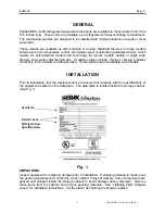
Kairak KRES Instruction Manual Download Page 11

KAIRAK 


Page 11 


- 11 - 

IM-ES-REV 5-09-06.doc5-09-06 

 
CONDENSING UNIT 

 
WARNING:  DISCONNECT ELECTRICAL POWER SUPPLY BEFORE CLEANING ANY 
PARTS ON THE UNIT. 

 
The condensing unit coil and filter must be cleaned regularly on self-contained models for 
optimal performance.  The operating environment will affect the required frequency of cleaning.  
However, both should be cleaned a minimum of once every three months.  Air must be able to 
freely circulate through the condenser. Unit performance and operating efficiency are 
significantly affected by the amount of air passing through the condenser.  Condenser fins that 
are clogged with dirt and debris greatly reduce required airflow.  

Failure to keep the coil fins 

and the air filter clean may cause premature compressor failure, which will not be 
covered by warranty.  (On models that contain filters, operating unit without filter will 
void warranty). 


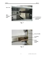
The condensing unit is located behind the louvered panel in the compressor compartment. 
Remove louvered panel by pulling on the bottom then lifting up and out. Remove rear access 
panel located in the back of unit.  A phillips head screwdriver is required to remove rear access 
panel.  Carefully clean dirt and lint from the condenser coil using a vacuum cleaner or soft 
brush; do not use a wire brush.   
 
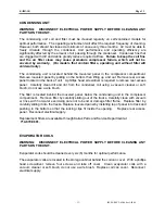
The filter is located behind the louvered panel, below the condensing unit in the compressor 
compartment.   Remove filter by carefully sliding out of the tracks. Carefully clean with vacuum 
or rinse with hot water exercising care not to bend or damage filter frame.  Replace filter by 
carefully sliding it into the tracks. Replace louvered panel by installing top of panel into track and 
pushing in the bottom so that the locking clips fit inside the opening.    Replace rear access 
panel.  Reconnect electrical supply. 
 
Replacement filters are available through Kairak Parts and Service Department at 
 

714-870-8661.


EVAPORATOR COILS 

 
WARNING:  DISCONNECT ELECTRICAL POWER SUPPLY BEFORE CLEANING ANY 
PARTS ON THE UNIT. 


Evaporator coils should be cleaned every six (6) months for optimal performance.   
 
The evaporator coils are located in the storage cabinet behind the coil can cover.  With a phillips 
head screwdriver, remove four screws and take off cover.  Clean evaporator coils with a 
vacuum cleaner or soft brush, do not use a wire brush.  Replace coil can cover.  Reconnect 
electrical supply. 


Summary of Contents for KRES

Page 1: ...Kairak IM ES REV 5 09 06 500 S State College Blvd Fullerton CA 92831 PN 4406010 1 A Div of ITW FEG LLC INSTRUCTION MANUAL KRES Equipment Stands Self Contained and Remote...

Page 2: ...tions include marine or flat top stainless steel back 6 inch casters and drawer locks Some options are not available on all models INSTALLATION Prior to installation test the electrical service to ass...

Page 3: ...LTER Remove louvered panel by lifting up and pulling out entire panel Slide the filter into the tracks located below the compressor compartment Be careful not to catch the filter on sharp edges when i...

Page 4: ...to the bottom of the cabinet with 4 or 6 depending on the model 6 32 x 3 8 phillips head screws Place the condensate evaporator in the heater bracket Slide the heater bracket into the mounting rails P...

Page 5: ...for refrigerant line brazing 50 50 or cold solder is not acceptable For system charge follow remote refrigeration system manufacturer s instructions ELECTRICAL CONNECTIONS Refer to the wiring diagram...

Page 6: ...nge this setting set the pins to desired off times Each pin represents 15 minutes Pins pulled out away from center of time clock represent refrigeration off Pins pushed toward center indicate refriger...

Page 7: ...perature settings are preset at the factory but local conditions may necessitate slight adjustments On self contained refrigerated models the temperature control shown in Fig 5 is located in the compr...

Page 8: ...ated units the temperature control should be set at 37 F with a 3 F differential This display should read between 34 F and 40 F The temperature control setting is locked to avoid unauthorized adjustme...

Page 9: ...used for an extended period of time disconnect the electrical power supply and the drawers to the storage cabinet As soon as the cabinet has warmed to room temperature wipe out the base interior MAIN...

Page 10: ...KAIRAK Page 10 10 IM ES REV 5 09 06 doc5 09 06 Fig 7 Fig 8 Cross Rail Lock Cross Rail Lock 1 on each side of drawer Drawer Module Liner Lock Black Clamping Knob Black Clamping Knob...

Page 11: ...n the back of unit A phillips head screwdriver is required to remove rear access panel Carefully clean dirt and lint from the condenser coil using a vacuum cleaner or soft brush do not use a wire brus...

Page 12: ...ously Door gaskets not sealing properly Condensing unit filter is dirty Evaporator coil is iced up or dirty Prolonged and or frequent door openings or door s ajar Excessive load of warm food placed in...

Page 13: ...to Kairak C O D via UPS or common carrier 5 YEAR COMPRESSOR WARRANTY Compressor manufacturer warrants compressor components for a period of twelve months from the serial number manufacture date Replac...

Reviews: