5
C. DRILLING THE HOLES
CAUTION:
Positioning and drilling must be done straight to avoid excessive
force being exerted on the lock which may result in the premature wearing of
its mechanical parts.
NOTE:
The latch is reversible on spring latch models 917, 919, 935, 938, and
929. Refer to the instructions in Section I, “Disassembling the Lock.”
Use a variable speed drill to prevent splintering the door or breaking the drill
bit. Begin drilling at a slow speed and increase the speed gradually until the tip
of the pilot bit emerges through the other side of the door. Repeat this proce-
dure from the opposite side of the door to complete the
7
⁄
8
" (22 mm) and 1
5
⁄
8
"
(41 mm) holes. Use a
1
⁄
8
" (3 mm) drill bit to make pilot holes for the three
mounting screws.
C-1
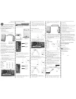
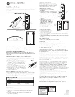
Drill the holes according to the template
(
See Figure 3-1
; right hand door shown).
All models require 5 holes:
(A) one
7
⁄
8
" (22 mm) hole
(B) one 1
5
⁄
8
" (41 mm) hole
(C) three
1
⁄
8
" (3 mm) holes for the mounting
screws.
Drill approximately
1
⁄
2
" (13 mm)
deep.
Key override models require one additional hole for the key cylinder:
(D) one
7
⁄
8
" (22 mm) hole.
D. INSTALLING THE KEY
CYLINDER
Shortening the cylinder tailpiece:
D-1
Determine the lock and riser plate you are
using then select the break line from the
table at right.
Lock A = Models 902, 906, 917, 935 for doors 1
3
⁄
8
" (35 mm) to 1
1
⁄
2
" (38 mm) thick
Lock B = Models 904, 910, 919, 938, 929 for
doors 1
3
⁄
4
" (44 mm) to 2
1
⁄
8
" (54 mm) thick
D-2
Hold the tailpiece firmly with a pair of pliers
(A) on the cylinder end of the tailpiece, just
beside the desired break line
(See Figures
4-1 and 4-2)
.
D-3
With a second pair of pliers (B), grip the tail-
piece at the other side of the line and bend up
and down until it breaks.
4
A. DETERMINING THE LOCK HANDING
Many of the installation instructions refer to the
handing of your door, so you should determine the
hand before starting the installation.
The hand of the door is determined with the door
in the closed position, from the exterior (pushbut-
ton side) of the door
(See Figure 1-1 and 1-2).
RH
- Right hand door. Door opens inward (push).
Hinged on the right side.
LH
- Left hand door. Door opens inward (push).
Hinged on the left side.
RHRB
- Right hand reverse bevel door. Door opens
outward (pull). Hinged on the right side.
LHRB
- Left hand reverse bevel door. Door opens outward (pull). Hinged on the
left side.
Once you have determined the handing of your
door, you should determine the distance above your existing primary lockset
where the auxiliary lock will be mounted – 8" to 10" (203 mm to 254 mm) is
recommended.
B. MARKING THE DOOR
The door must be closed.
B-1
Remove the template from the center of this
booklet.
B-2
Fold the template on the solid line for an
inswing door, if you are not using a riser plate.
Fold the template on the dashed line for an
outswing door, or if you are using a riser plate
with an inswing door.
B-3
Tape the template securely to the inside sur-
face of the door so that the indicated fold is
aligned with the edge of the door
or door stop
,
if one is present.
Figure 2-1
shows the inside
of a left hand door;
Figure 2-2
shows the
inside of a right hand door.
B-4
Use a center punch (or similar marking tool)
to make the marks for drilling the five holes
precisely at the points indicated on the
template; there is a sixth hole (A) for key
override models.
B-5
Remove the template.
1-1
1-2
RH
LH
RHRB
LHRB
A
B
1
5
⁄
8
" (41 mm)
A
7
⁄
8
" (22 mm)
C
1
⁄
8
" (3 mm)
D
7
⁄
8
"
(22 mm)
C
1
⁄
8
" (3 mm)
C
1
⁄
8
" (3 mm)
2-1
3-1
A
2-2
Lock
Riser Plate
Break Line
A
---
1
B
----
1
A
1/4" (6 mm) side
2
A
3/8" (10 mm) side
2
B
1/4" (6 mm) side
2
B
3/8" (10 mm) side
3
4-1
4-2
B
A


