background image

Page 10

INSTALLATION GUIDE - REMOTE ACCESS CONTROLLER RAC 4XT • PK3191_10_14

a hammer & screwdriver / awl, and from 
the inner side of the enclosure tap out the 
small metal disk.

3.   

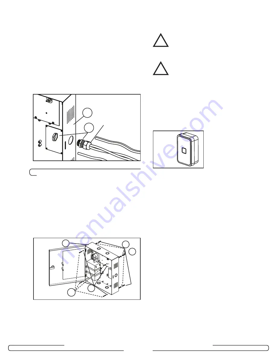
Based on the amount of wires to be 
routed, attach the appropriate strain 
relief to the enclosure as shown in 
Figure 10. 

Do not attempt to route an 

excessive amount of wires. If extra 
strain reliefs are required please 
contact Kaba Ilco

.

4.2

 Installation & Wiring Procedures

Step 5: Mounting the RAC 4XT enclo-
sure

Install the enclosure in the desired location 
using the appropriate items from the hardware 
bag.

NOTE:

  For easier access it is recommended 

to remove the access door before 
installation.

Step 6: Mounting and wiring card 
reader(s)

For installation of the card reader(s) follow the 
appropriate steps listed below, depending 
on the type of card reader and configuration 
being installed.

CAUTION:
 Do not exceed the maximum cable length 
indicated by the manufacturer of the 
products being connected.

CAUTION:
 Refer to the wiring label on the access 
door, the wiring diagram & tables in Annex 
A, or the detailed peripherals connections 
in Annex B.

IMPORTANT:

Every wire must pass through a strain 
relief as connected in step 4.

Model R79K-XXX Contactless card 

reader installation

1.  Remove the back plate and use it to mark 

the holes for the cables and screws.

Alternatively, the drilling template DT-
514800 included with the reader can be 
used.

NOTE:

  Do not use the actual drawing from 

Annex H of this manual to mark the 
hole locations as this drawing is not 
to scale.

2.  Drill the holes in the wall according to the 

diameters indicated on the drilling template 
in Annex H, based on the type of surface 
the reader is being installed on.

Metal surface mounting:

 install the back 

plate onto the wall with the metal screws 
provided in the installation hardware bag.

Drywall surface mounting:

 tap the 

wall inserts (provided in the installation 
hardware bag) into the wall using a rubber 
mallet. Install the back plate onto the wall 
with the wood screws provided.

3.  Connect the included cable to the terminal 

block of the reader as shown in Annex A, 
Table 1. Ensure that the correct wire color 
is attached to the correct terminal block 
connection.

Figure 10

A

V

Compression 
Nut

A

U

T

S

X

Figure 11

OR

!

!

Figure 12

Summary of Contents for RAC 4XT

Page 1: ...INSTALLATION GUIDE ILCO Remote Access Controller RAC 4XT ...

Page 2: ...er s 11 Step 7 Connect peripheral wiring 12 Step 8 Relay Expansion Board outputs wiring 14 Step 9 Power adaptor connection 15 5 0 Settings and Operation 16 5 1 Testing 16 5 2 Hotel ID Initialization 16 5 3 Hotel ID Re initialization 16 5 4 Programming and Auditing 17 5 5 Battery Back up Replacement 18 5 6 New Battery Back Up Installation 18 5 7 Power Failure 19 5 8 Loading Recommendations 19 5 9 S...

Page 3: ...s as well as for any maintenance procedures CAUTION Wear safety glasses when using any tools Technical Support For technical assistance call 800 906 4526 514 340 9025 OR Visit the Kaba Support Website www kabalodgingsupport com NOTE This equipment has been tested and found to comply with Part 15 of the FCC Rules These limits are designed to provide reasonable protection against harmful interferenc...

Page 4: ...cal locking or control devices where a stand alone electronic lock is not practical It provides ingress egress access control that can be programmed with the full range of Solitaire 710 710 II Generation 760 770 790 or System 700 features The system can control any door or access point up to 500 feet 150m away when using a swipe insert or extended range contactless reader and up to 40 feet 12m awa...

Page 5: ...stems F Cam lock with Key to provide secure locking and to control access to the RAC 4XT enclosure Optional components G Battery Back up 12 VDC battery providing up to 4 hours of operation in the event of a power failure H Relay Expansion Board interface board providing 8 relay outputs that can be used to control relay equipped equipment As example it can be used with an elevator to call the eleva...

Page 6: ...comes in a satin stainless steel finish For use in elevator panels only where enough space permits minimum 4 5 depth required 2 2 2 2 Contactless Card Reader The Contactless Card Reader is a small vertically mounted unit that protrudes from the wall and is used with RFID based keycards 2 2 3 Locking devices The RAC 4XT controller PCB can provide one or multiple when used with a relay expansion boa...

Page 7: ...oller PCB jumpers card reader type dependent Card Reader s NOTE Type of card reader s dependent on system configuration ordered J Swipe reader see Figure 4 J Insert reader see Figure 6 may require additional tools as per PK3166 included with the reader J Contactless reader see Figure 7 Locking Device NOTE Locking device s dependent on system configuration ordered K Electric strike L Electromagneti...

Page 8: ...ools required not supplied Additional tools may be required dependent on the peripherals being installed The list below covers the installation of the RAC 4XT enclosure only Safety glasses Ink marker Electric drill 9 64 3 5 mm drill bit 7 32 5 5 mm drill bit 1 4 6 5 mm drill bit 3 8 9 5 mm drill bit Philips screwdriver 2 Slotted screwdriver 3 32 tip width Adjustable wrenches Crimp tool 18 22 AWG P...

Page 9: ... RAC 4XT PK3191_10_14 3 2 Exploded View Controller Box Hardware Bag Power Adaptor Peripherals Optional Devices 7 8 9 C 4 5 6 F 1 2 3 0 L J P R O North American International N M A B G C H Figure 9 X 5x 4x 2x 4x 4x 1x 1x T S U V W K L E F Z 2x Y 3x 2x D ...

Page 10: ...ard readers must be placed within 500 feet 150 m from the RAC 4XT enclosure while contactless card readers R79 1N1 must be placed within 40 feet 12 m of the reader power source Readers should be installed in an obvious location at an ergonomic height near the access door or elevator being controlled Swipe card reader The space to use the swipe reader must be large enough to allow for adequate swip...

Page 11: ...iring diagram tables in Annex A or the detailed peripherals connections in Annex B IMPORTANT Every wire must pass through a strain relief as connected in step 4 Model R79K XXX Contactless card reader installation 1 Remove the back plate and use it to mark the holes for the cables and screws Alternatively the drilling template DT 514800 included with the reader can be used NOTE Do not use the actua...

Page 12: ...ing tap the wall inserts provided in the installation hardware bag into the wall using a rubber mallet Install the back plate onto the wall with the wood screws provided 3 Connect the included cable to the terminal block of the reader as shown in Annex A Table 1 Ensure that the correct wire color is attached to the correct terminal block connection NOTE For additional strain relief it is recommend...

Page 13: ... insert card reader is 4 5 1 Ensure all tools are available as indicated in manual PK3166 T included with the insert card reader 2 Referencing the drilling template DT 512152 included with the reader mark the location of the holes to be drilled and the rectangular cut out to be made NOTE Do not use the actual drawing from Annex F of this manual to mark the hole locations as the drawing is not to s...

Page 14: ...f the electric strike or electromagnetic lock 1 2 If installing an electric strike install the diode across the terminals of the locking device using the crimp connectors provided in the hardware bag if needed IMPORTANT Do not reverse the diode polarity as indicated on the wiring diagram CAUTION To prevent a possible short the diode must not be in contact with electric strike If required cut the d...

Page 15: ...ep 8 Relay Expansion Board outputs wiring Refer to Annex B Figure 12 for sample wiring diagram The relay expansion board provides 8 relay contacts for wiring control of relay enabled peripherals such as an elevator The board only provides normally open or normally closed dry contacts so no power is provided by the board for peripherals When a relay expansion board is connected the controller PCB s...

Page 16: ...pply inputs as shown in Annex A Table 8 2 Route the wires out of the enclosure to the AC power source and secure the wires recommended with tie wraps 3 Crimp the fork terminals supplied in the hardware bag to the end of the wires and connect them to the power adaptor screw terminals Step 10 Completing the installation 1 If the access door was removed reinstall the door to the RAC 4XT enclosure 2 B...

Page 17: ...e panel verify that the electromagnetic lock or a fail safe electric strike is deactivated when the fire alarm is active open input 13 If a battery back up is equipped when fully charged remove the main AC power adaptor and verify proper RAC 4XT operation 5 2 Hotel ID Initialization 1 Create an initialization keycard with the hotel s FDU or ATLAS system 2 Use the programmed initialization keycard ...

Page 18: ... connector serial port J5 on the controller PCB Refer to figure 19 for the positions of the relevant connectors 2 For step by step programming instructions refer to the Kaba Ilco Lodging Access Control Reference Manual ATLAS Programming For ease of programming the IPM kit for RAC PN 064 511161 can be used by attaching the IPM to the RAC with the Velcro provided in the kit Cut a piece of each type ...

Page 19: ...ng that the red wire connects to the positive terminal and the black wire connects to the negative terminal 9 Reconnect the power adaptor and or turn on the main AC power to the RAC 4XT 5 6 New Battery Back up Installation If the original system did not have a battery back up but one is desired later order kit 064 511889 K and follow the steps below 1 Turn off the main AC power to the RAC 4XT or d...

Page 20: ...pansion board will return to their normal state Any peripheral connected to the relays will then be either in a normally open NO or normally closed NC state dependent on the wiring 5 8 Loading Recommendations CAUTION Do not exceed the load limitations of the RAC 4XT system The maximum recommended load for all output relays in the RAC 4XT system is 1 Amp at 30 VDC The tamper switch rating is 1 Amp ...

Page 21: ... SW3 NO COM NC NO COM NC NO COM NC NO COM NC NO COM NC NO COM NC NO COM NC NO COM NC ON SW3 ON Card Reader Ingress Card Reader Egress Tamper Switch Exit Device for Push Bar Pannex and Motion Detector See Instruction Booklet J Power Adaptor For Europe UK Autralia 24 VDC For North America 24 VAC Unswitched AC Power Source For readers refer to reader install sheets Note Connections required are depen...

Page 22: ...NO XFMR 1 YELLOW 1 ON OFF ON North America BLACK WHITE ON OFF OFF ON OFF ON BLACK Wire Color International Table 5 ON OFF 1 2 1 2 XFMR 1 XFMR 2 8 3 NO Type If bypass switches are ON Relays are bypassed GREEN LEDs are OFF If bypass switches are OFF GREEN LEDs are ON Controller Board can activate relays SW1 4 SW3 4 Adaptor Table 8 COM Signal ID XFMR 2 AC Fail 3 Signal DC OUT 2 DC OUT 1 Low BAT 3 Con...

Page 23: ...O 12V GND LBAT ACF GND 12V GND J1 J15 J8 J7 J6 J14 J13 J12 J16 J17 J18 J19 J2 J3 12V 1 2 3 1 2 3 1 1 2 3 1 2 3 1 2 3 1 2 3 4 1 2 3 1 2 3 4 1 2 1 2 3 2 3 1 2 3 4 1 2 3 4 GND DOOR GND TPR GND REX GND REM CGND TX RX GND J8 J7 J6 1 2 3 4 1 2 3 4 1 2 3 4 R79 1N1 Reader Max 50 Feet R79 1N1 Reader Max 50 Feet R79 1E1 Reader Max 500 Feet R79 1E1 Reader Max 500 Feet Same Connections Except RED Wire 5V 5V 1...

Page 24: ...Wires Connector Black Wire Note To automatically unlock the door in case of fire remove the Fire Alarm Bypass wire and connect J18 to the Fire Alarm panel as per Fire Alarm Panel Wiring diagram see Annex B Figure 10 In this case the Electric Strike MUST be powered from the RAC 4XT s 12V output as shown in this diagram 12 V Supply For Locking Device Fire Alarm Bypass Wire see Note RAC 4XT PCB 5V NO...

Page 25: ...3 4 1 2 3 4 1 2 3 4 Locking Device Supply 12V or 24V GND GND 12V or 24V Ground External Power Supply Output Voltage Locking Device Note 1 If the locking device is inductive such as a strike place a diode across the locking device s terminals as shown in the strike wiring diagrams Note 2 See Note 2 Dependent on locking device type may connect to Normally Open NO or Normally Closed NC IMPORTANT Kaba...

Page 26: ...e Unlock or the REX input depending on the required functionality In both cases the wires should be connected to the Normally Open contact of the Exit button In general a Motion Detector or a maual override should be connected to the REX input J8 pins 3 4 NO COM NC Remote Unlock EXIT NO COM NC RAC 4XT PCB 5V NO 5V GND 12V 1 2 3 1 2 3 4 NC COM GND FIRE GND COM NC NO LOW BATT AC FAIL NO C DC BAT INP...

Page 27: ...larm Panel 5V NO 5V GND 12V 1 2 3 1 2 3 4 NC COM GND FIRE GND COM NC NO 12V GND LBAT ACF GND GND DOOR GND TPR GND REX GND REM CGND TX RX GND 12V GND J1 J15 J8 J7 J6 J14 J13 J12 J16 J17 J18 Normally Closed Output See Notes 1 and 2 When the RAC 4 4XT is connected to a Fire Alarm Panel it must be connected to a Normally Closed dry contact output If the Fire Alarm Panel connection is not required plac...

Page 28: ...power to the RAC 4XT to ensure proper Relay Expansion Board functionality Note 2 The relay outputs are fail safe Accordingly they are energized in their normal state and the relay status LED is ON Upon power failure or when the Fire alarm input is activated when connected to a Fire Alarm panel the relay state will change and access will be automatically granted The relay status written NC or NO is...

Page 29: ...e shielded cables for the readers 2 Connect the shield wire of the reader cable to the Ground wire 3 Connect the wires to the Mounting screw of the RAC Remove the paint under the mounting screw of good electrical contact 4 Ensure the Relay Expansion Board if applicable has no more than 30VDC from elevator or other power source Power Adapter RAC 4XT ENCLOSURE Shielded Cable Shielded Wire of Cable P...

Page 30: ...wer supply DC ON red LED is OFF Verify the wiring between the power supply and the RAC 4XT controller Verify that the power supply output is not shorted RAC 4XT enclosure s panel door Power Status LED is OFF Verify that the power supply is powered both AC ON and DC ON LEDs are on Verify the LED wiring to the power supply RAC 4XT enclosure s panel door Battery Status LED is OFF Verify the wiring po...

Page 31: ...ler press the Reset switch SW1 or disconnect and reconnect the power Verify the wiring to the reader As a card is being used with the reader verify that the data present LED D34 Ingress D35 Egress illuminates during use Verify that the card is encoded properly Verify that the time is correct both on the RAC 4XT and the FDU or Atlas If not do a Reset Lock Time Re program the RAC 4XT No response to ...

Page 32: ...put is not active Input contact closed Fire Alarm LED D47 is on Verify the wiring to the locking device If a diode is installed on the locking device verify the polarity If the locking device Relay LED D31 does not turn on Verify that the Request to Exit or Remote Unlock activation unlocks the door Verify that the card is encoded properly Verify that the RAC 4XT is not in Lockout mode Verify that ...

Page 33: ...the relays are not bypassed the bypass switches SW1 and SW4 on the Relay Expansion Board should be off Verify that the RAC 4XT is not in passage mode Relay Expansion Board relays do not activate Activate the manual bypass switches SW1 and SW3 on the Relay Expansion Board and verify that the relays are activated and the corresponding LEDs turn off De activate the manual bypass Verify that the addre...

Page 34: ...nctionality 2 D46 LEDs should blink If not reset the RAC 4XT Controller press the Reset switch SW1 or disconnect and reconnect the power Verify that the cable between the RAC 4XT and the FDU or IPM is connected properly If the RAC 4XT is not initialized Initialization LED D41 is OFF Follow the instructions in Section 5 2 Hotel ID Initialization If the RAC 4XT was already initialized it may need to...

Page 35: ...Page 34 INSTALLATION GUIDE REMOTE ACCESS CONTROLLER RAC 4XT PK3191_10_14 6 0 Annex E Drilling Templates for Swipe Card Reader ...

Page 36: ...INSTALLATION GUIDE REMOTE ACCESS CONTROLLER RAC 4XT PK3191_10_14 6 0 Annex E Drilling Templates for Swipe Card Reader NOTE If swipe reader is model R71 2XX with 4 mounting holes please contact Technical Support ...

Page 37: ...Page 36 INSTALLATION GUIDE REMOTE ACCESS CONTROLLER RAC 4XT PK3191_10_14 6 0 Annex F Drilling Template for Insert Card Reader ...

Page 38: ...Page 37 INSTALLATION GUIDE REMOTE ACCESS CONTROLLER RAC 4XT PK3191_10_14 6 0 Annex G Drilling Template for Contactless Card Reader ...

Page 39: ...mm INCH mm A INSTALLATION WITH DRYWALL INSERT 7 32 5 6 1 1 2 38 1 INSTALLATION WITH METAL SCREW 9 64 3 6 1 2 12 7 B 5 8 15 9 DRILLING TEMPLATE RFID WALL READER R79K SURFACE MOUNT MODULE SHEET DATE 21AU14 UNE VERSION FRANCAISE DE CE DOCUMENT EST DISPONIBLE SUR DEMANDE 1 OF 1 ECN 15174 DT 514800 REV 1 R 7301 Décarie Boul Montréal Qc Canada H4P 2G7 www kaba ilco com A A B DO NOT REPRODUCE CONTACT CUS...

Page 40: ...Montréal QC H4P 2G7 Customer Service and Technical Support T 1 877 468 3555 F 514 735 6589 General Information www kabalodging com Online Consumable Orders www ilcostore com To access all of our easy steps please visit our Support Website www kabalodgingsupport com ...

Reviews: