Kaba Mauer 82132/3 CB30 Series Mounting Instructions Download Page 17


Version 02/15/2016 

Page 37 of 40 

Mounting instructions 82132/3xxx CB 30 
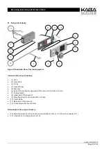
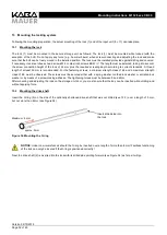


13.3.4 

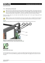
Fastening the base part 

 
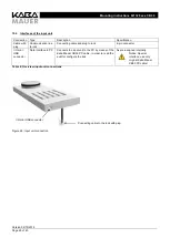
The  Combi  B  30  base  part  (11)  is  now  screwed  onto  the  storage  unit  door  using  the  three  enclosed  screws  (9),  as  shown  in 
Figure 31, (for the drill hole specification, see chapter 12.2). Ensure tidy cable routing: 
Depending on  the position  of the  cable  passage  hole, it may  be  necessary  to  pass  the  connecting  cable  (12)  below  the  base 
part (11) to the cable passage hole. In doing so, do not squeeze or damage the cable (see note in chapter  13.3.3), but make 
sure that it is laid below the base part up to the passage hole in the cabinet. 
 

Notice:

 The turnament to fix the base part (11) must not exceed 

1,3 Nm


Notice:

  To  fasten  the  base  part,  only  the  enclosed  screws  (9),  whose  screw  head  size  match  exactly  the  input  unit, 

should be used! Should you use any other screws, you have to make sure that the screw head height does not exceed 
2.6 mm, since otherwise the rotary handle (7) cannot be mounted or dismounted! 
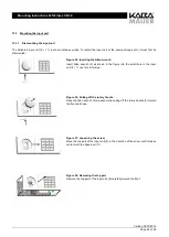


13.3.5 

Inserting the batteries 

 
Insert two batteries (no. 14) of type AAA / LR 03 and ensure correct polarity; otherwise, the lock (1) will not function and damage 
may  occur.  It  is  highly  recommended  using  high-quality  brand  batteries  and  replace  them  as  a  precaution  every  24  months  
at the latest. 


Summary of Contents for 82132/3 CB30 Series

Page 1: ...etal input unit Mounting instructions EN CLAVIS Deutschland GmbH Schillerstra e 47 51 34117 Kassel Telefon 49 0 561 988 499 0 Fax 49 0 561 988 499 99 E Mail info tresore eu Internet www tresore eu www...

Page 2: ...30 12 3 Drive shaft 31 13 Mounting the locking system 32 13 1 Mounting the lock 32 13 2 Mounting the drive shaft 32 13 3 Mounting the input unit 33 13 3 1 Dismounting the input unit 33 13 3 2 Adjusti...

Page 3: ...o the upper part of the keypad frame 34 Figure 40 After removing the top holder turn around the fitting 34 Figure 41 Carefully pull out the keypad sub assembly toward the back 34 Figure 42 Mounting th...

Page 4: ...the locking system must be de energized during wiring i e the batteries in the input unit and power supply units must be removed Otherwise the lock electronics may become damaged The locking system i...

Page 5: ...on switch Change over contact 30V DC 0 1 A Pin1 Common Pin2 Normally Closed Pin3 Normally Open Silent alarm 3 Max 24 V DC 25 mA Pin6 Collector Pin7 Emitter Lock Input signal Only configurable via the...

Page 6: ...lock 6 pin connector I O mini USB connector Data interface to PC Connects the input unit to the PC by means of the Kaba Mauer CB30 PC cable in order to read the audit or configure the lock As pre ass...

Page 7: ...rew for arresting the upper part of the input unit F H 2 9 x 6 5 mm 7 Rotary handle 8 Upper part of the input unit 9 Mounting screws for base part M4 x 6 0 mm 10 Cable binder 11 Base part of the input...

Page 8: ...ns that are outside the data shown in Figure 28 must be coordinated separately with certifiers test institutes The position of the key hole the dimensions and the resulting required space for the inst...

Page 9: ...ecure storage unit it is recommended inserting the Kaba Mauer key guide see Figure 29 or the Kaba Mauer key carrier guide see Figure 30 In these cases taking into consideration DIN 2768 mH the key in...

Page 10: ...able 11 if necessary In addition to that another cutout is required in the cabinet door used as cable passage for the connecting cable 12 between lock 1 and input unit 8 11 The size of the cable passa...

Page 11: ...een the lock mounting plane and the input unit mounting plane 20 mm immersion depth into the input unit 26 5 mm immersion depth into the lock tolerance 0 2 mm see Figure 32 Shorten the drive shaft 2 o...

Page 12: ...30 mm is recommended For the fastening screws a minimum strength class of 4 8 and a maximum strength class of 8 8 must be observed The screws must be secured either with a spring washer toothed lock...

Page 13: ...en wrench Insert Allen wrench 5 as shown in the figure into the small hole in the input unit 8 11 as far as it will go Figure 36 Pulling off the rotary handle Keep the Allen wrench 5 pressed while pul...

Page 14: ...assembly from its top holders Next remove the keypad unit carefully from its bottom holders see Figures 42 and 43 and then take it out of the top part of the operating unit 8 toward the back if possi...

Page 15: ...y handle on the left keypad on the right Not required Rotary handle at the top keypad at the bottom 90 counterclockwise Rotary handle at the bottom keypad at the top 90 clockwise Rotary handle on the...

Page 16: ...rt 11 via the green miniplug JST 5 pin see Figure 43 step I Notice In doing so ensure correct alignment of the plug to the socket Under no circumstances must the plug be inserted twisted and with forc...

Page 17: ...make sure that it is laid below the base part up to the passage hole in the cabinet Notice The turnament to fix the base part 11 must not exceed 1 3 Nm Notice To fasten the base part only the enclose...

Page 18: ...Mounting the rotary handle Check the O ring 3 seat once again 5 8 mm from the front edge of the shaft Then insert the rotary handle 7 and lock it into place In doing so make sure that in the locked s...

Page 19: ...ntioned for the user in the instructions of the secure storage unit or in additional documents In addition to that the set master code can be documented in the operating instructions of the lock For m...

Page 20: ...0 Mounting instructions 82132 3xxx CB 30 CLAVIS Deutschland GmbH Schillerstra e 47 51 34117 Kassel Telefon 49 0 561 988 499 0 Fax 49 0 561 988 499 99 E Mail info tresore eu Internet www tresore eu www...

Reviews: