


Version 02/15/2016
Page 32 of 40
Mounting instructions 82132/3xxx CB 30
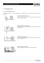
13 Mounting the locking system
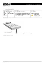
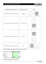
Following the mounting preparation, the actual mounting of the lock (1) and of the input unit (8 + 11) can take place.
13.1
Mounting the lock
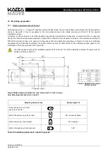
The lock (1) must be mounted in the secure storage unit as follows: The lock (1) must be mounted while locked (with the
exception of the bolt). Do not apply any force (e.g., hammer blows) when screw-connecting and adjusting the lock and make
sure that the bolt can be freely moved in the installed position. The lock must be installed protected against drilling and covered,
if necessary. Use steel cheese head screws M 6 or steel inch screws BSW ¼“. The length must be selected, taking into account
the screw connection height of the lock of 24 mm plus the required screwing depth according to current standards. A thread
length of at least 30 mm is recommended. For the fastening screws, a minimum strength class of 4.8 and a maximum strength
class of 8.8 must be observed. The screws must be secured either with a spring washer, toothed lock washer or serrated lock
washer or by means of a screw-locking adhesive. The tightening torque must be between 5 and 6 Nm.
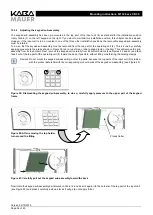
After mounting and adjusting the lock on the storage unit door, you must ensure that the key can be inserted without tilting and
without applying force.
13.2
Mounting the drive shaft
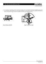
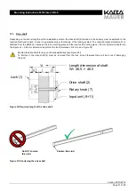
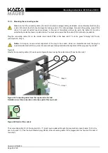
Insert the O-ring (3) on the side of the optionally shortened drive shaft that was not drilled (see 12.3) over a length of 5 mm,
but not more than 8 mm (see Figure 34).
Figure 34: Mounting the O-ring
NOTICE
: Under no circumstances should the O-ring be inserted over a length of more than 8 mm! Faultless functioning
of the lock can only be insured if the O-ring is positioned correctly!
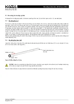
Next, the drive shaft (2) is inserted into the lock with its drilled side pointing forward (see Figure 34) as far as it will go.
Insert drilled side into
the lock
approx. 5mm
Maximum: 8 mm