WinKey USB SMT Assembly and Operation Guide - Version 1.5 12/26/2017 Pg 4
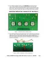
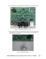
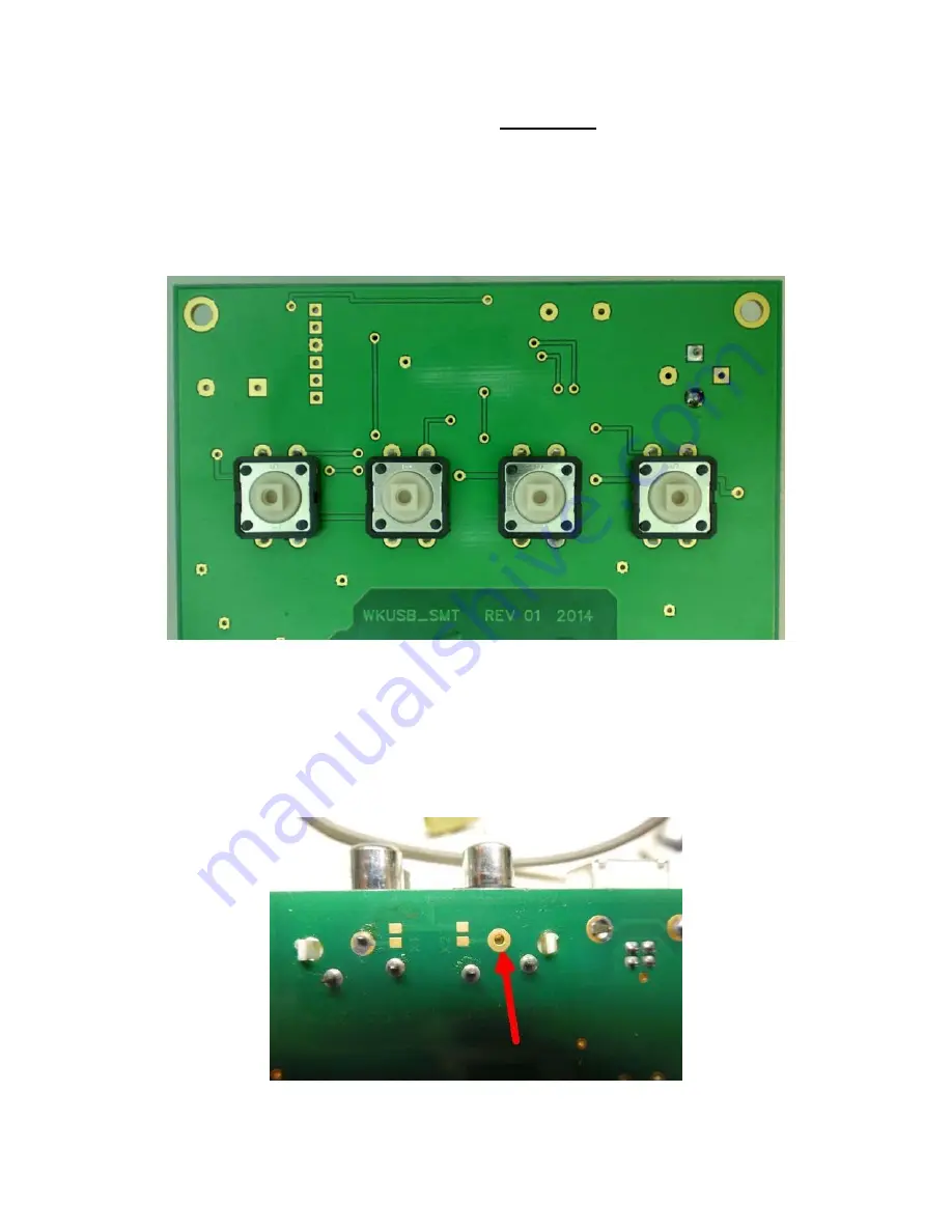
6) Now install four pushbutton switches on the
!! BOTTOM !!
side of the PC board as
shown in figure 3. Make sure the switches are flush to bottom of the board before
soldering from the top of the board. After soldering, attach the square push-button caps,
with red on S1, which is on the left when the phono jacks face away from you, switches
facing up. Press firmly until they snap in place, just a small amount of force is required.
SWITCHES MOUNT ON THE BACK OF THE PCB !!!
Figure 3 – Pushbutton switches installed correctly
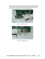
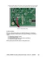
7) Now install the four-way RCA phono jack block at J3. Don’t solder the pins yet !! We have
had several reports of problems with this connector. It is very easy to install the connector
hastily and have one or more of its pins bend under and not make it through the PC
board. Here is a bottom view of such a connector showing five pins soldered and one not
because the pin did not go through the board. Don’t let this happen, it is very difficult to
recover from this mistake.
Figure 4 – Watch out !! Bent pin on RCA connector block


