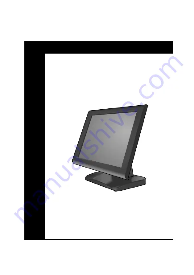
background image


K

K

-

-

M

M

o

o

n

n

i

i

t

t

o

o

r

r


T

T

o

o

u

u

c

c

h

h


P

P

O

O

S

S


M

M

o

o

n

n

i

i

t

t

o

o

r

r


U

U

s

s

e

e

r

r


M

M

a

a

n

n

u

u

a

a

l

l

Version 1.0

Summary of Contents for Touch POS

Page 1: ...K K M Mo on ni it to or r T To ou uc ch h P PO OS S M Mo on ni it to or r U Us se er r M Ma an nu ua al l Version 1 0 ...

Page 2: ......

Page 3: ...safety notices and the User Manual carefully before using the product Keep the box and packaging in case the product needs to be shipped in the future Follow the product and warning label instructions Any changes or modifications that do not follow the instructions in this manual will void this productʹs warranty P Po ow we er r S Su up pp pl ly y S Sa af fe et ty y N No ot te es s To avoid electr...

Page 4: ...orage temperature may go above 70 C 158 F as this can cause damage to the equipment M Ma ai in nt te en na an nc ce e Gently wipe screen with a clean soft hair lens brush or a lint free cloth Do not apply pressure to the screen while cleaning Do not spray any liquid directly onto the screen or the casing of the K Monitor Touch POS Monitor Chemical cleaners have been reported to cause damage on the...

Page 5: ...rference to radio communications However there is no guarantee that interference will not occur in a particular installation If this equipment does cause harmful interference to radio or television reception which can be determined by switching the equipment on and off the user is encouraged to try to correct the interference by one or more of the following measures Reorient or relocate the interf...

Page 6: ...dous waste Isolated collection and proper recovery of your electronic and electrical waste equipment at the time of disposal will allow us to help conserving natural resources Moreover proper recycling of the electronic and electrical waste equipment will ensure safety of human health and environment For more information about electronic and electrical waste equipment disposal recovery and collect...

Page 7: ...4 OSD Control 5 Unpacking 6 Chapter 2 Getting Started 7 Pre installation Notice 7 Setting Up Your Monitor 8 POS Terminal Installation 8 MSR SCR Device Installation Optional 9 System Assembly and Disassembly 11 Cable s Replacement 11 Appendix Technical Information 14 Specifications 14 Frequently Asked Questions FAQ 15 ...

Page 8: ......

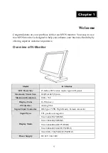
Page 9: ...o of f K K M Mo on ni it to or r Model K Monitor LCD Panel Size 15 Inches TFT Active matrix type LCD panel Maximum Visual Size 246 H x184 5 V mm Maximum Resolution 1024 x 768 Display Color 16 7M max PC Interface Analog VGA Signal Input Connector DB Type 15 PIN High Density Female connector Signal Sync TTL positive or negative VGA 640x350 70 85HZ VGA 720x400 70 85HZ VGA 640x480 60 72 75 85HZ VGA 80...

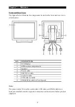
Page 10: ...r views of K Monitor NO DESCRIPTION 1 LCD display 2 MSR module compartment 3 Speaker 4 Power cable 5 DB15 VGA cable 6 Audio In cable 7 USB cable for MSR 8 DB9 RS232 cable for Touch panel Note The power cable VGA cable audio cable USB cable and RS232 cable have been pre installed onto the respective connectors on the monitor before product shipment ...

Page 11: ...Chapter 1 Welcome 3 S Si id de e V Vi ie ew w S Si id de e V Vi ie ew w You can adjust the LCD panel up to an angle of 90 ...

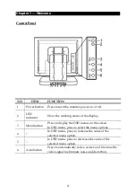
Page 12: ...of the display 3 Menu button Press to display the OSD menus on the screen In OSD menu press to select the menu options 4 In OSD menu press to increase the value of the selected menu option 5 In OSD menu press to decrease the value of the selected menu option 6 Auto button Press to automatically resize center and fine tune the video signal to eliminate noise and distortion ...

Page 13: ...Chapter 1 Welcome 5 O OS SD D C Co on nt tr ro ol l Brightness and Contrast setting Sound Control setting RGB Color setting Clock and Phase setting Function setting Exit ...

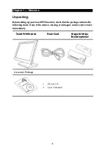
Page 14: ...ontact your vendor immediately Before setting up your touch POS monitor check that the package contains the following items If any of the items is missing or damaged contact your vendor immediately Touch POS Monitor Touch POS Monitor Power Cord Power Cord Magnetic Stripe Reader optional Magnetic Stripe Reader optional n np pa ac ck ki in ng g Accessory Package 1 Driver CD 2 User s Manual ...

Page 15: ... is turned on 2 If using K Monitor in a dusty environment clean the monitor regularly 3 The USB device connector is Hot Swap capable Do not plug in or unplug any connection except USB devices when the power is on 4 The spill proof design of K Monitor conforms to IP 43 standard Front panel only 5 Always seek the help of authorized service personnel in disassembling the monitor The manufacturer will...

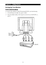
Page 16: ...t ti io on n e et tt ti in ng g U Up p Y Yo ou ur r M Mo on ni it to or r P PO OS S T Te er rm mi in na al l I In ns st ta al ll la at ti io on n To connect your monitor to the POS terminal POS PC do the following 1 Connect the power cable into a power outlet 2 Plug the related cables to the respective connectors on the POS PC as shown Power Outlet POS PC ...

Page 17: ...on n O Op pt ti io on na al l To install the MSR SCR device onto the K Monitor do the following 1 Remove the MSR module compartment A 2 Thread the MSR SCR USB cable through the MSR SCR bracket B 3 Affix the casing screw to the bracket and hook the MSR SCR device onto the casing screw head as shown C Then push down to secure it in place 4 Secure the MSR SCR device onto the bracket with one M3 screw...

Page 18: ...Chapter 2 Getting Started 10 5 Firmly connect the MSR SCR USB cable to the connector on the right side of the monitor E 6 Attach and secure the MSR SCR device onto the monitor with the two screws F ...

Page 19: ...b bl ly y C Ca ab bl le e s s R Re ep pl la ac ce em me en nt t To replace the cable s do the following 1 Carefully place the monitor side down on a cushioned surface to protect the display from damage 2 Remove the two screws on the back cover 3 Pull the back cover to the direction of the arrow to remove it ...

Page 20: ...Chapter 2 Getting Started 12 4 Remove the two screws M4 10 A and two thumbscrews B as shown 5 Remove the connectors cover ...

Page 21: ...replace 7 Remove the routing plate 8 Remove the adapter and route the cable s as shown to remove it from the monitor Routing plate 9 Replace the cable s with a new one Then follow the above mentioned steps in reverse to complete the replacement A Ap pp pe en nd di ix x ...

Page 22: ...ast Ratio 600 1 Typical Brightness 250 cd m2 Response Time 10 Ms Typical Viewing angle L R 45 degree Viewing angle U D 30 to 10 degree Plug Play Function Compatible with DDC 1 2B Rule Display Color 16 7M max PC Interface Analog VGA Signal Input Connector DB Type 15 PIN High Density Female connector Signal Sync TTL positive or negative Display Mode VGA 640 x 350 70 85HZ VGA 720 x 400 70 85HZ VGA 64...

Page 23: ...ecifications are subject to change without notice F Fr re eq qu ue en nt tl ly y A As sk ke ed d Q Qu ue es st ti io on ns s F FA AQ Q PROBLEM SOLUTIONS Connect the power cord properly Check if the monitor is turned on or not Press the Power button to turn on the monitor The monitor does not work Make sure all cables are connected properly The display image is too dark Adjust the Brightness in the...

Reviews: