background image

English

Deutsch

Français

28


XM-EX90

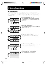
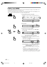
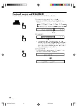
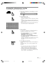
Dividing a track (DIVIDE)

A track can be divided into desired number of tracks by adding track markings in the middle, in the
desired points or where you want to search later.
This makes it possible to assign track numbers after recording medley music or FM broadcast. The
track numbers after the divided track are incremented automatically.

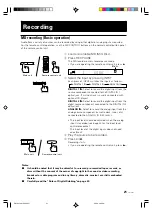
1

Press EDIT to select “DIVIDE”.

Each press of EDIT switches the editing functions as
follows.

DIVIDE

JOIN

MOVE

ALL ERASE

MD total playing time display

ERASE

1 2 3 4 5
6

Blinks.

2

Press SET.

Blinks.

1 2 3 4 5
6

Blinks.

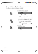
3

Play the track to be divided.

Select the track number by pressing </

4

 or 

¢

/>

then press 

£

.

Blinks.

1 2 3 4 5
6

Blinks.

Example) When track No. 3 is selected

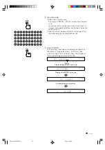
4

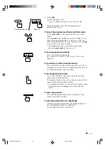
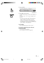
Press SET when a point where you want to
divide the track comes.

“POSITION” is displayed then the track marking fine-
adjustment display appears.

Blinks.

1 2 3 4 5
6 7

Blinks.

Increments by 1.

Example)Track No. 3 and 4 blink and the 3-second

section from the divided point will be
played repeatedly.

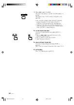
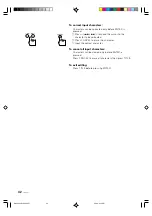
• When the track has been divided as desired, go to

step 

6

.

• If the track has not been divided as desired, fine-

adjust the track marking position. Go to step 

5

.

• If you notice that the selected track number is wrong,

press CANCEL and select the correct track number.

EDIT

SET

SET

EN26-42.XM-EX90[J]/1

98.6.4, 0:09 PM

28

Summary of Contents for XM-EX90

Page 1: ... 001A J 1 2 3 4 5 6 7 8 9 10 10 CLOCK TIMER FM MODE MUTING SLEEP SET CANCEL REPEAT CD 1 CD 2 CD 3 DOWN PLAY MODE REPEAT S A BASS FADE MUTING TREBLE BASS BALANCE L R DISPLAY TRACK MARKING PLAY MODE UP CD CONTROL MD CONTROL TAPE CONTROL VOLUME RM SEEX90MU REMOTE CONTROL TUNER AUX POWER XM EX90 MINIDISC RECORDER INPUT CD REC RECPAUSE CANCEL SAMPLING RATE CONVERTER STANDBY REC LEVEL DISC LOADING MECHA...

Page 2: ...is no guarantee that interference will not occur in a particular installation If this equipment does cause harmful interference to radio or television reception which can be determined by turning the equipment off and on the user is encouraged to try to correct the interference by one or more of the following measures Reorient or relocate the receiving antenna Increase the separation between the e...

Page 3: ...ower cord and consult your dealer Do not insert any metallic object into the Unit For safe use observe the following Avoid moisture water and dust Do not set your machine in moist or dusty places Avoid high temperatures Do not expose your machine to direct sunlight or set near a heating device Do not block the vents Poor ventilation may damage your machine So do not block the vents or put the unit...

Page 4: ... Moving a track MOVE 32 Erasing a track ERASE 34 Erasing all tracks in an MD ALL ERASE 36 Assigning titles to an MD and its tracks 38 Assigning titles while playback or recording 41 Remote Control of the othr Components 43 Remote control of the other optional components from the provided remote control unit 43 Remote controlling the amplifier tuner 44 Remote controlling the CD player and cassette ...

Page 5: ...dex 1 POWER button Press to switch the power between ON and STANDBY STANDBY indicator The indicator is off while the power is ON and lights up when the power is in STANDBY mode 2 Display 3 MD insertion slot Load an MD through this slot 4 Remote control sensor 5 4 REC LEVEL buttons Press to skip to the beginning of a desired track to fast forward or fast reverse a disc or adjust the recording level...

Page 6: ... function recording editing function etc 4 Repeat indicators Shows the repeat mode REPEAT ALL Lights when all tracks in an MD or all tracks in the program are played repeatedly REPEAT 1 Lights when a single track is played repeatedly 5 Play mode indicators PROGRAM Lights in the program play mode RANDOM Lights in the random play mode 6 Track indicators Shows the number of tracks in the MD 7 Input m...

Page 7: ...ach jack with the provided COMPU LINK 3 SYNCHRO jack of another component Either jack can be used for the connection 3 DIGITAL IN jacks Connect using the provided optical digital cable 1 Connect with the DIGITAL OUT jack of the CD player 2 Connect with the DIGITAL OUT jack of your DBS tuner etc 4 AC POWER CORD receptacle Connect the provided AC power cord COMPU LINK 3 SYNCHRO ANALOG DIGITAL IN AC ...

Page 8: ... 6 7 8 9 10 10 CLOCK TIMER FM MODE MUTING TUNER AUX SLEEP SET CANCEL REPEAT CD 1 CD 2 CD 3 DOWN PLAY MODE REPEAT FADE MUTING S A BASS TREBLE BASS BALANCE L R DISPLAY TRACK MARKING PLAY MODE UP CD CONTROL MD CONTROL TAPE CONTROL VOLUME RM SEEX90MU REMOTE CONTROL 3 2 1 POWER S A BASS FADE MUTING VOLUME RM SEEX90MU REMOTE CONTROL 4 5 SPACE EDIT TITLE ENTER SET CANCEL SMALL LETTER POWER EN03 13 XM EX9...

Page 9: ...lude the all track repeat mode and 1 track repeat mode DISPLAY Switches the information shown on the character display TRACK MARKING Switches the track assignment during recording between automatic and manual 4 MD editing control buttons EDIT Switches the editing functions TITLE Assigns a title to a MD or its track ENTER Enters the editing contents in memory SET Sets the point where a track is div...

Page 10: ...r or other heat emmitting appliance In direct sunlight Do not place the CD player on top of the amplifer tuner In a place warmer than 35 C 95F In a bathroom kitchen or other area with steam humidity or hot water In a place with lots of static electricity or dust In an unstable area Near appliances that receive electronic wave broadcasts such as a television or tuner Batteries R03 UM 4 AAA 24F x 2 ...

Page 11: ...the equipped with Compu Link remote control system CD player connect to the DIGITAL IN 1 jack of this unit Compu Link cable Connect to the COMPU LINK 3 SYNCHRO jack of another equipped with Compu Link remote control system CD player COMPU LINK 3 SYNCHRO ANALOG DIGITAL IN AC POWER CORD 1 2 RIGHT IN REC OUT PLAY LEFT OPTICAL BAND VOLUME UP KEY MODE DOWN INPUT PHONES INTEGRATED AMPLIFIER TUNER STANDB...

Page 12: ...sed at an angle of 60 or if there are objects between the remote control and the remote sensor Cautions Observe the following to avoid battery leakage or explosion If the range or effectiveness of the remote control decreases replace the batteries using R03 UM 4 AAA 24F type dry cells Do not use an old battery together with a new one Do not use different types of batteries together Do not disassem...

Page 13: ...ain unit before pressing a button If the remote control unit is used from an oblique direction or if there is an obstacle between it and the main unit the remote control signals may not reach the main unit When using the normal control buttons When using the editing control buttons Normal control button panel Editing control button panel STANDBY XM EX90 MINIDISC RECORDER DISC LOADING MECHANISM INP...

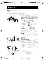
Page 14: ...s and total playing time of the disc Shortcut When the power is in the STANDBY mode inserting an MD turns the power on and the MD is pulled in automatically 2 Press 8 Playback starts The indicator lights up If you are using the remote control unit press Shortcut When the power is in the STANDBY mode pressing 8 or on the remote control unit turns the power on and starts MD playback automatically In...

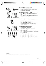
Page 15: ...t reverse These operations cannot be controlled from the remote control unit To select and play a desired track Main unit remote control unit 1 Press 4 or to select a track number 2 Press to start playback Remote control unit Press then immediately compose the track number of the desired track To select track No 5 Press 5 To select track No 15 Press 10 then 5 To select track No 20 Press 10 then 10...

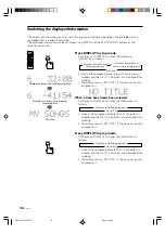
Page 16: ...f the disc has no title assigned to it When a track has already been selected Each press of DISPLAY switches the information as follows Track No and its playing time Track title A track title composed of more than 11 characters is scrolled and the first 11 characters are displayed after scrolling The display shows NO TITLE if the track has no title assigned to it Press DISPLAY in play mode Each pr...

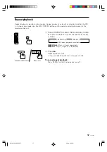
Page 17: ... to select the repeat play mode Each press of REPEAT switches the repeat play modes as follows REPEAT ALL REPEAT 1 Off Repeat playback canceled REPEAT ALL Plays all tracks repeatedly REPEAT 1 Plays a single track repeatedly 2 Press Repeat playback starts If you are operating the main unit press 8 To cancel repeat playback Press REPEAT so that the indicators turn off Main unit Remote control unit R...

Page 18: ... The display shows PROGRAM and the PROGRAM indicator lights up If some tracks have already been programmed the track number and program number of each track will be displayed Lights PROGRAM Each press of PLAY MODE switches the play modes as follows PROGRAM RANDOM Off Continuous play PLAY MODE can be pressed only in stop mode Be sure to stop MD before pressing PLAY MODE 4 Select desired track numbe...

Page 19: ...you make a mistake in programming Press CANCEL in stop mode to clear the last track in the program until the track you programmed by mistake and re program tracks from that point To exit program play mode Press PLAY MODE in stop mode and select any play mode other than PROGRAM The program contents remain in memory even after the program play mode has been exited The program contents are cleared fr...

Page 20: ...the play modes as shown below PROGRAM RANDOM Off Continuous play PLAY MODE can be pressed only in stop mode Be sure to stop MD before pressing PLAY MODE 3 Press Random playback starts If you are operating the main unit press 8 Random playback stops after having played every track once To exit random play mode Press PLAY MODE in stop mode and select any play mode other than RANDOM To repeat random ...

Page 21: ...rom the digital source component connected to the DIGITAL IN 2 optical jack ANALOG IN Select to record the analog input from the analog source component cassette deck tuner etc connected to the ANALOG IN REC jacks The input level should be adjusted when the analog input is recorded see page 22 for the input level control procedure The input level of the digital inputs does not need adjustment 4 Pl...

Page 22: ... period the display returns to the record pause mode display 2 Adjust the input level by pressing 4 or LEVEL 1 L REC R Adjust so that these segments blink at the peak level The level indicator blinks when the input level is too high Adjust the input level as described above Too high an input level results in distorted recording The input level can be adjusted in the range from 50 to 0 To display t...

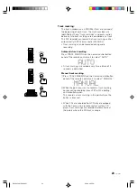
Page 23: ...ote control unit to select AUTO A track marking is recorded every time a blank of 3 seconds is detected Manual track marking 1 Press TRACK MARKING on the normal control button panel of the remote control unit to select MANUAL 2 When the point you want to record a track marking comes during recording press SET on the editing control button panel This records a track marking in the point where the b...

Page 24: ...3 Press CD REC The CD player and MD recorder start simultaneously and synchronized recording starts The DIGITAL 1 input is selected automatically and the DIGITAL 1 indicator lights up To stop recording Press CANCEL to stop recording Synchronized recording of the analog input This method is available only when the Compu Link connection page 48 has been made among the components 1 Load a recordable ...

Page 25: ... analog input Press so that ANALOG IN appears on the display see page 21 5 Press 4 or to adjust the input level See To adjust the analog input level on page 22 When recording from the cassette deck start playing the tape before proceeding to the input level control After the input level control rewind tape to the beginning of the music to be recorded 6 Press 8 Recording starts If you are operating...

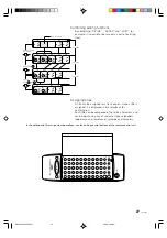
Page 26: ... track marking Moving a track MOVE Page 32 This function moves a track by reordering the track numbers Erasing a track ERASE Page 34 This function erases a specified track After the erasure the subsequent tracks are justified and their track numbers are decremented automatically Erasing all tracks ALL ERASE Page 36 This function erases data in a disc entirely Editing Functions C D A 1st B 2nd 3rd ...

Page 27: ... input using any of character types alphabets uppercase and lowercase symbols and numerals In the editing and title assignment operations use the editing control buttons of the remote control unit B C A A B A A C a b c A B C A a c A B C A a c b a c Dividing track A into 3 tracks Part to be erased Erasing track Joining tracks and Track No Track No Track No 1st 1st 1st 1st 2nd 2nd 2nd 3rd 2nd 3rd 3r...

Page 28: ...s 1 2 3 4 5 6 Blinks 3 Play the track to be divided Select the track number by pressing 4 or then press Blinks 1 2 3 4 5 6 Blinks Example When track No 3 is selected 4 Press SET when a point where you want to divide the track comes POSITION is displayed then the track marking fine adjustment display appears Blinks 1 2 3 4 5 6 7 Blinks Increments by 1 Example Track No 3 and 4 blink and the 3 second...

Page 29: ... change made above is entered temporarily in the memory The display shows EDITING 1 2 3 4 5 6 7 7 Press 0 to eject the MD The data in the memory is written in the MD before it is ejected The display shows UTOC writing during MD write operation Be careful not to apply impact to the MD recorder during writing data in the memory in the MD Otherwise the recording may be unplayable later The data in th...

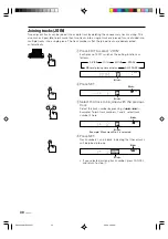
Page 30: ...ches the editing functions as follows DIVIDE JOIN MOVE ALL ERASE MD total playing time display ERASE 1 2 3 4 5 6 Blinks 2 Press SET Blinks 1 2 3 4 5 6 Blinks 3 Select the track to be joined with the previous track Select the track number by pressing 4 or Example To join track numbers 1 and 2 select track number 2 here Blinks 1 2 3 4 5 6 Blinks Example When track No 2 is selected 4 Press SET Track ...

Page 31: ... careful not to apply impact to the MD recorder during writing data in the memory in the MD Otherwise the recording may be unplayable later The data in the memory is written in the MD also when the power is switched to the STANDBY mode while EDITING is being displayed To exit editing Press EDIT before pressing ENTER in step 5 To restore the original tracks from the track obtained by joining Use th...

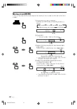
Page 32: ...s 1 2 3 4 5 6 Blinks 3 Select the track number to be moved then press SET Select the track number by pressing 4 or Blinks 1 2 3 4 5 6 Blinks Example When track No 2 is to be moved If you selected a wrong track number press CANCEL and select the correct track number 4 Select the movement destination track number then press SET Select the track number to be given to the selected track by pressing 4 ...

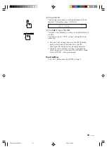
Page 33: ...d The display shows UTOC writing during MD write operation Be careful not to apply impact to the MD recorder during writing data in the memory in the MD Otherwise the recording may be unplayable later The data in the memory is written in the MD also when the power is switched to the STANDBY mode while EDITING is being displayed To exit editing Press EDIT before pressing ENTER in step 5 ENTER INPUT...

Page 34: ...4 5 6 Blinks Blinks 3 Select the track number to be erased then press SET Select the track number by pressing 4 or Blinks 1 2 3 4 5 6 Blinks Blinks Example When track No 2 is to be erased Blinks 1 2 3 4 5 6 Blinks Example When SET is pressed If you selected a wrong track number press CANCEL and select the correct track number If the display shows TRACK PROTECTED the selected track has been protect...

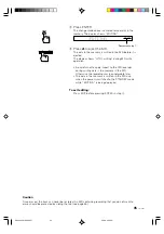
Page 35: ... to apply impact to the MD recorder during writing data in the memory in the MD Otherwise the recording may be unplayable later The data in the memory is written in the MD also when the power is switched to the STANDBY mode while EDITING is being displayed To exit editing Press EDIT before pressing ENTER in step 4 Caution Once erased the track can never be restored An MD containing recording that ...

Page 36: ...ASE MD total playing time display ERASE 1 2 3 4 5 6 Blinks 2 Press SET 1 2 3 4 5 6 Blinks If the display shows TRACK PROTECTED the selected track has been protected against accidental erasure by other component than the MD recorder in use If you still want to erase the track go to step 3 If you will not erase it press EDIT 3 Press ENTER The change made above is entered temporarily in the memory Th...

Page 37: ...he memory in the MD Otherwise the recording may be unplayable later The data in the memory is written in the MD also when the power is switched to the STANDBY mode while EDITING is being displayed To exit editing Press EDIT before pressing ENTER in step 3 Caution Once erased the tracks can never be restored An MD containing recording that you do not want to erase should be protected by sliding the...

Page 38: ...play shows DISC NO TITLE 1 2 3 4 5 6 Blinks Scrolled If a disc title has already been assigned the title is displayed If you want to assign only the disc title go to step 3 If you want to assign the track titles press 4 or to select the track to be titled then go to step 3 To vary track numbers in the backward direction press 4 1 2 3 4 5 6 Blinks Scrolled 3 Press SET The cursor starts blinking 1 2...

Page 39: ...ing the character input keys Up to 64 characters can be input per title 5 Press ENTER The characters input above are entered temporarily in the memory The display shows EDITING then scrolls the input title and finally shows the number of tracks and total playing time of the MD 1 2 3 4 5 6 Blinks Display before ENTER is pressed 1 2 3 4 5 6 Display after ENTER is pressed 1 2 3 4 5 6 Scrolled display...

Page 40: ...ten in the MD also when the power is switched to the STANDBY mode while EDITING is being displayed To correct input characters Characters can be corrected only before ENTER is pressed 1 Press 4 or to move the cursor to the character to be corrected 2 Press CANCEL to erase the character 3 Input the correct character To cancel all input characters Characters can be cleared only before ENTER is press...

Page 41: ...emory The display shows EDITING If it is during playback the track will be played repeatedly until ENTER is pressed Pressing ENTER stops the playback If it is during recording recording continues even after ENTER is pressed If ENTER is not pressed until the end of the track the characters input before the end of the track are recorded 4 Press 0 to eject the MD The data in the memory is written in ...

Page 42: ...he cursor to the character to be corrected 2 Press CANCEL to erase the character 3 Input the correct character To cancel all input characters Characters can be cleared only before ENTER is pressed Press CANCEL to erase all characters then press TITLE To exit editing Press TITLE before pressing ENTER CANCEL EN26 42 XM EX90 J 1 98 6 4 0 10 PM 42 ...

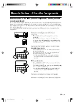
Page 43: ...trol mode to the amplifier tuner mode Switching the POWER button s control mode Amplifier tuner mode Press POWER and 1 on the normal control button panel simultaneously This makes it possible to switch the amplifier tuner power between ON and STANDBY In this mode the MD recorder power cannot be switched between ON and STANDBY by remote control MD recorder mode Press POWER and 10 on the normal cont...

Page 44: ...ontrol system directly Amplifier tuner control buttons 1 2 3 4 5 6 7 8 9 10 10 CLOCK TIMER FM MODE MUTING TUNER AUX SLEEP SET CANCEL REPEAT CD 1 CD 2 CD 3 DOWN PLAY MODE REPEAT FADE MUTING S A BASS TREBLE BASS BALANCE L R DISPLAY TRACK MARKING PLAY MODE UP CD CONTROL MD CONTROL TAPE CONTROL VOLUME RM SEEX90MU REMOTE CONTROL POWER EN43 60 XM EX90 J 1 98 6 4 0 18 PM 44 ...

Page 45: ... the timer or clock BASS Used when controlling low frequencies After pressing BASS adjust the level by pressing R or L TREBLE Used when controlling high frequencies After pressing TREBLE adjust the level by pressing R or L BALANCE Used when controlling the balance between the left and right channels After pressing BALANCE adjust the level by pressing R or L R L Press when setting the balance trebl...

Page 46: ...or CD 3 sets the numeric keys to the CD control mode Numeric keys 1 to 10 10 Used to select a track number directly Track No 5 Press 5 Track No 15 Press 10 then 5 Track No 20 Press 10 then 10 Track No 32 Press 10 three times then press 2 Cassette deck control buttons Starts playback 7 Stops playback or recording 1 In play mode skips to the beginning of a tune Music Scan In stop mode fast forwards ...

Page 47: ...disc number Press CD 1 CD 2 or CD 3 4 Select a track number using the numeric keys 5 Program other tracks by repeating steps 3 and 4 6 Press Program playback starts Recording of cassette tapes 1 Load the tape for use in recording in the tape tray of the cassette deck 2 Press The cassette deck enters record pause mode 3 Play the source to be recorded 4 Press or Recording starts PLAY MODE CD 1 CD 2 ...

Page 48: ...mplicated and their linked operation impossible Then isn t it possible to combine single component and control them as simply as an integrated audio system The Compu Link remote control system is the response to such a requirement The components in the JVC EX series are equipped with jacks named COMPU LINK 3 COMPU LINK jacks By connecting the COMPU LINK jacks of these components they can be contro...

Page 49: ...rol unit The remote control unit provided with the amplifier tuner can also be used to control the CD player or cassette deck See Remote Control of the Other Optional Components on page 43 Synchronized recording Recording can be started automatically in synchronism with the start of playback of a source component Timer operation The timer function built into the amplifier tuner can be used to star...

Page 50: ...o have a copy restriction rule for protecting the copyright and the SCMS has been established as a result SCMS Serial Copy Management System With a view to protecting the copyright the SCMS restricts the number of generations permitted for copying of signals in the digital form between digital audio equipment to only one generation Caution Because of this rule the MD obtained by recording a CD on ...

Page 51: ...ordable MD that can be recorded onto and the playback only MD that can exclusively be played back Although both types of discs are played in the same way that is by irradiating a laser beam on the disc and reading signals from the reflected light the ways they are recorded are completely different Playback only MD This type of disc is used in prerecorded MD software marketed in music stores It can...

Page 52: ...uring MD Mini Disc playback In case the optical laser cannot read disc signal due to vibration the actually reproduced audio is not interrupted because the data stored in the guard memory is available UTOC User Table Of Contents The recordable MD Mini Disc contains the recording of UTOC User Table Of Contents in addition to music data itself The UTOC includes the information on the positions the t...

Page 53: ...pt is made to join tracks that cannot be joined The MD is abnormal damaged The disc has no available space or the number of tracks has reached 254 An abnormality occurred during recording No MD is loaded An attempt is made to digitally dub a CD ROM Video CD etc An attempt is made to record on or edit a playback only MD The MD is protected against accidental erasure A track has been protected again...

Page 54: ...space of at least 2 seconds for recording data even when it is shorter than 2 seconds When a large number of non used spaces below 2 seconds are produced in a disc as a result of the above the available recording time in the disc is shortened The MD uses a unique data recording format that is different from the formats used by Cassettes tape and DAT Due to the restrictions imposed by this MD recor...

Page 55: ...rusted in these places On a beach or sandbox The disc surface may be scratched or damaged if grit penetrates through an opening on the cartridge Periodical maintenance When the cartridge gets dusty or dirty wipe with a soft dry cloth Do not open the shutter The shutter is usually locked to prevent opening Do not force to open it or the disc may be destroyed To protect important recording A recorda...

Page 56: ...MD is protected against accidental erasure DISC PROTECTED is displayed in this case The batteries are exhausted The batteries are inserted with wrong polarity There is an obstacle between the remote control unit and remote control sensor The remote control sensor is under direct sunlight POWER is set to the amplifier tuner mode Condensation is produced inside the MD recorder immediately after star...

Page 57: ...ic range Wow flutter Input terminals Analog Digital Output terminal Analog Power requirements Power consumption Demensions Mass Accessories Received optical Remote control unit 1 Batteries R03 UM 4 AAA 24F 2 Audio pin cord 2 Optical digital cord 1 Compu link cable 1 AC power cord 1 ANALOG IN pin jack OPTICAL DIGITAL IN square optical connector jack Terminal name Reference input level Minimum input...

Page 58: ...cessories for your JVC product you may contact your local JVC Dealer Or from the 48 Continental United States call toll free 800 882 2345 QUALITY SERVICE HOW TO LOCATE YOUR JVC SERVICE CENTER TOLL FREE 1 800 537 5722 Dear customer In order to receive the most satisfaction from your purchase read the instruction booklet before operating the unit In the event that repairisnecessary orfortheaddressne...

Page 59: ...rovided with the products or if the model or serial number has been altered tampered with defaced or removed 2 Initial installation and installation and removal for repair 3 Operational adjustments covered in the Owner s Manual normal maintenance video and audio head cleaning 4 Damage that occurs in shipment due to act of God and cosmetic damage 5 Signal reception problems and failures due to line...

Page 60: ...VICTOR COMPANY OF JAPAN LIMITED J VC 0598TTMWSTOZK EN EN43 60 XM EX90 J 1 98 6 4 0 19 PM 60 ...

Reviews: