background image

23

5. Registering connection points

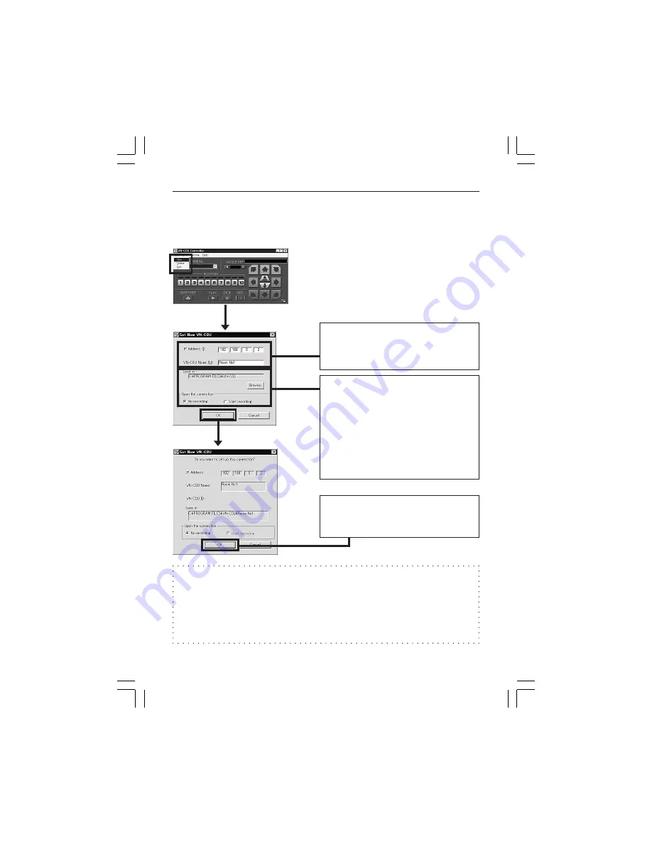
Start the VN-C3U controller (VN-C3U.exe). Select New from the File item
in the menu and then specify the connection point.

Enter the IP address and name of the
V N - C 3 U   c o n n e c t i o n   p o i n t .
(192.168.0.2. is used as an example
in the diagram.)

The folder "VN-C3U Name" will be
created automatically in the folder
specified here. Recorded files will be
saved here. (Refer to page 43
concerning recording.)
"Upon the connection" determines
whether or not recording will start
automatically upon the connection of
VN-C3U.

If the settings are completed, press
OK to end registration of connection
point.

Advice

Copying registered connection points to another PC, VN-C3U connection
points data is saved to a file with the .dat extension inside the folder created
by VN-C3U controller.

All the connection points settings can easily be copied to another PC by
copying the file with the .dat extension.

VM-C3U̲E.65J

00.4.7, 5:34 PM

23

Summary of Contents for VN-C3U - V-networks Pan/tilt/zoom Camera

Page 1: ...m panying the appliance RISK OF ELECTRIC SHOCK DO NOT OPEN CAUTION Information for USA This device complies with part 15 of the FCC Rules Changes or modifications not approved by JVC could void the user s authority to operate the equipment Due to design modifications data given in this instruction book are subject to possible change without prior notice AVERTISSEMENT POUR EVITER LES RISQUES D INCE...

Page 2: ...s etc con nected to this device or power plugs during a thunder storm because this can result in electrical shock When installing this device maintain a space of 10cm or more between this device and the wall Also keep other de vices at a distance to ensure good radiation Internal heat can result in fire WARNING Warning This is a class A product In a domestic environment this product may cause radi...

Page 3: ...ation is ignored and the product is erroneously handled This represents the contents in which the probabilities for injury to be inflicted are assumed and the contents in which material damages to be sustained are assumed if this symbol indication is ignored and the product is erroneously handled Numerous symbols are employed as indication in the precautions for safety precautions for handling and...

Page 4: ...could cause overturning and result in injury or damage Use special caution with children Use only the specified accessories Use only the accessories specified in the instruction manual with this device The use of other accessories can result in fire or electrical shock Have your local dealer perform an internal inspection once every three years Accumulated dust inside this device can eventually re...

Page 5: ...es and product names mentioned in this instruction manual are the trademarks or registered trademarks of the respective companies Before Recording or Saving Important Images Due to provisions of the copyright law images recorded and saved from TV broadcasts and recorded tapes etc and recorded and saved images of printed materials such as posters etc cannot be used for any purpose other than person...

Page 6: ...g a work PC IP address 22 Enabling the IP address setting 22 Registering connection point 23 Controller Software Operation 24 Starting connections and changing connection points 24 Connecting from the Settings file 25 Controller 1 26 Controller 2 28 Controller 3 29 Deleting connection points 30 Changing resolution and inverting the image 31 Image quality adjustment 32 Transmission frames 34 Changi...

Page 7: ...ribed below is necessary for operation of the VN C3U A PC running Microsoft Windows95 98 or NT CPU Pentium 133MHz or equivalent 200MHz or more recommended Memory capacity 32MB or more 64MB or more recommended Hard disk capacity 20MB or more Display and video card 640 x 480 dots or more High Color 1024 x 768 dots or more True Color recommended 10BASE T LAN board connection cables LAN Environment 10...

Page 8: ...ightly from the natural colors due to the principle of the automatic tracking color balance circuit When any bright object such as a lamp etc is photographed white bands may appear above and below the bright object This is called smearing a phenomenon caused by the characteristics of the individual pixels and is not a malfunction When panning and tilting the VN C3U do not apply force to any part o...

Page 9: ...Connect the VN C3U to the network and turn the power on 3 Set the VN C3U IP address When setting the VN C3U IP address be sure to contact the network administrator for assignment or approval When installing the second and following units reboot the PC and then return to step 2 4 Enable the VN C3U IP address Turn the VN C3U power off and then on again 5 Register the connection point This registers ...

Page 10: ...ly be installed as shown in the diagram below or inverted Do not install facing sideways Tilted installation is not possible 1 Attach the ceiling fixer with the P hole pointing toward the front of the camera 4 Mount the VN C3U on the ceiling fixer by rotating clockwise then tighten the screw of the camera body fixer 2 Mount the camera body fixer on the VN C3U 3 Attach the drop prevention wire of t...

Page 11: ...e IP address at the factory therefore if the power of multiple VN C3U units is turned on at the same time address duplication will occur and correct access will not be possible Always turn the power on for only one unit at a time If address duplication occurred perform the proper processing and wait for 10 min or more or turn off the power of all units on the network and then turn the power on aga...

Page 12: ...Length use cables with a length of 50m or less Recommended model UL1007 UL1015 or equivalent cable with wire equivalent to AWG 22 AWG 18 Sensor insert button External device OUT 1 External device OUT 2 External device IN Caution External noise may affect the alarm working properly even with a cable length of 50m or less In such cases it is necessary to either change to the use of shielded cable to...

Page 13: ...l and Network in that order 1 Select the TCP IP item then click on Properties 2 Before making a change always make a note of the original IP address Change the IP address to 192 168 0 3 3 Click on OK and then reboot the PC Set the subnet mask to a value suitable for the setting operation If the value is unknown check with the network administrator VM C3U E 65J 00 4 7 5 34 PM 14 ...

Page 14: ...tware Load the VN C3U Controller CD ROM into the CD ROM drive The setup program is in the JVC folder on the CD ROM Execute JVC Setup exe and follow the displayed instructions to setup the software VM C3U E 65J 00 4 7 5 34 PM 15 ...

Page 15: ...unit of the VN C3U at the top of the body depending on the installation conditions This setting reduces flicker under fluorescent lighting Specify 50Hz or 60Hz in accordance with the power supply frequency used in the installation area The camera ID corresponds to the identification code located on the VN C3U body Only alphanumerics can be entered The user does not participate directly Normally co...

Page 16: ...reen shown below will be displayed when the password button of the V NETWORKS setup tool is clicked Enter the current password In the case of new password setting nothing need be entered The characters entered will be indicated by asterisks When setting a password or changing the password enter the same password as above and below Nothing need be entered when password setting is being cancelled Th...

Page 17: ...ol for the fundamental settings When the Alarm button of the V NETWORKS setup tool is clicked the screen shown below will be displayed Caution When VN C2U or VN C1U is controlled from VN C3U controller the alarm setting is not available The procedure for the alarm settings is explained on the following page VM C3U E 65J 00 4 7 5 34 PM 18 ...

Page 18: ...arm out and Go to a preset position one of the 10 preset positions are available When the Alarm 1 and Alarm 2 receive signals in sequence use the Relay Alarm Function to make the different settings from the above mentioned Alarm 1 and Alarm 2 settings Place a check beside Use Relay Alarm and specify the alarm occurrence sequence and the time interval VM C3U E 65J 00 4 7 5 34 PM 19 ...

Page 19: ...he output value will change to Low Initialization Determine whether or not the alarm signal will be output one time when the power is turned on Set the values of Out port setting in accordance with the device to which the output is to be sent Retry Determines the number of retries 1 3 to be made when alarm input arrives Alarm force output Press the Output button for compulsory alarm output from th...

Page 20: ...yed The VN C3U controller has been started and is connected to the VN C3U subject to setup Checks are placed at Settings and Alarm Reg PCs can be deleted from the broadcast client list by selecting the IP address and pressing Delete Return to Alarm Setting window by pressing OK Caution Once the PC is deleted from the Broadcast client list the alarm does not function VM C3U E 65J 00 4 7 5 34 PM 21 ...

Page 21: ...t Search button is pressed a list of the V NETWORKS IP addresses currently connected to the network will be displayed Timeout is used to set the search time and can be set to 0 30 sec Caution When your own PC and a V NETWORKS of a different subnet are connected on a LAN connection will not be possible even if the search is successful In such cases change to an appropriate IP address on your PC and...

Page 22: ...files will be saved here Refer to page 43 concerning recording Upon the connection determines whether or not recording will start automatically upon the connection of VN C3U If the settings are completed press OK to end registration of connection point Advice Copying registered connection points to another PC VN C3U connection points data is saved to a file with the dat extension inside the folder...

Page 23: ...nts Refer to Software Installation on page 17 for the installation procedure When the VN C3U controller VN C3U exe is executed a logo will be displayed and then the following screen will appear Connection points can be selected from this pulldown menu VM C3U E 65J 00 4 7 5 35 PM 24 ...

Page 24: ...e File Types tab Enter an explanation in the Description of type box Example Dat file 3 Enter dat in the Associated Extensions box Click on New and then enter open in the Action box 4 Specify VN C3U exe in the Application used to perform action box Example C Program Files VN C3U VN C3U exe Caution This function cannot be used if the dat extension has already been specified as the file type for ano...

Page 25: ...ected VN C3U Pan tilt Zoom in Zoom out operation buttons The Pan Tilt operation angle step of connected VN C3U can be changed by clicking on the left and right buttons Pan Tilt position can be changed with the Pan Tilt operation buttons 8 buttons Zoom in Zoom out is performed by one step for each click of zoom button If you keep pressing the button Zoom in Zoom out can be performed continuously Pa...

Page 26: ...nt becomes around the center or screen Caution It is not possible to move beyond the Pan Tilt limits but this is not a malfunction Caution During the Pan Tilt operation the images may pause for a few seconds This is because the position correction function is automatically being operated and this is not a malfunction VM C3U E 65J 00 4 7 5 35 PM 27 ...

Page 27: ...t a i l s r e f e r t o Snapshot function on page 46 The size of VN C3U controller can be smaller by pressing this button It is possible to switch between the normal and smaller controller Smaller Controller Name of connected VN C3U Memorized position display Pan tilt operation buttons Connection point selection pulldown menu Position memory change button Caution During the position memory operati...

Page 28: ...tion angle step can be set by clicking the value and directly enter any value After entering changing the value press the Enter key If the cursor is briefly positioned over the VN C3U name a balloon display of VN C3U names will be displayed Creating new connection points Refer to Registering connection points on page 25 VM C3U E 65J 00 4 7 5 35 PM 29 ...

Page 29: ... menu and then select Delete Select a connection point to be deleted and then click on OK Make sure the desired point is being deleted and then press OK Caution The connection point cannot be recovered once it is deleted VM C3U E 65J 00 4 7 5 35 PM 30 ...

Page 30: ... 240 or 640 480 Depending on the installation select Normal or Upside Down On screen resolution change The resolution can also be changed on the screen with the following procedure Click the right button of the mouse on the screen and select one of the following 160 x 120 320 x 240 or 640 x 480 VM C3U E 65J 00 4 7 5 35 PM 31 ...

Page 31: ...lity The frame rate is in direct proportion to the compression rate Compression rate Low Medium High Image quality High Medium Low Frame rate Low Medium High This is set to the factory default value Click on OK to validate a setting change Refer to the following pages for details concerning image quality settings VM C3U E 65J 00 4 7 5 35 PM 32 ...

Page 32: ...olor balance Move the slide bar to the right to emphasize blue or to the left to emphasize red Full Auto This the Auto Manual switch When the check is removed the following three items will be switched to the Manual setting Gain Adjustment of the gain of the internal amp Use only when light is insufficient Contrast Adjustment of the contrast Brightness Adjustment of the brightness VM C3U E 65J 00 ...

Page 33: ...e actual frame rate depends on the operational environment PC LAN phone line etc and may be different from the transmission frame rate In practice the higher transmission frame rate is set up the more bandwidth is required Therefore try to set the lower transmission frame rate if relatively low bandwidth is available for VN C3U VM C3U E 65J 00 4 7 5 35 PM 34 ...

Page 34: ...of these memory buttons in which the status set in step 1 is to be memorized 3 Press OK to close the position memory setting window Caution When VN C2U or VN C1U is controlled from VN C3U controller the Lens Setting is not available The position memory 1 6 is available for VN C2U VN C1U uses a fixed type lens When the zoom scroll bar is set to the Tele end the lens position may not be the same aft...

Page 35: ...ght entering the camera will be kept constant When Manual is selected the brightness of the screen will be kept constant The scroll bar is used to perform the respective settings When Auto is selected from Focus the scroll bar will become inoperative Operation of the scroll bar is possible when Manual is selected Advice For locations where many people are passing by or operation of zoom at Tele we...

Page 36: ...s page Select Settings from the menu then select Alarm Settings There are four functions as follows Message Pop up Pop up the message entered in the text box Up to 100 letters can be entered Recording start Start recording the images Play a wave file Play a specified wave file Any wave files can be specified from the Browse button Execute a program file Execute a specified program file Any execute...

Page 37: ... setting in this page Caution When a large wave file wav is selected the alarm operation may be delayed depending on the PC specifications Try to select a relatively small wave file In order to enable the Alarm 1 Alarm 2 and or Relay Alarm setting it is necessary to 1 Select ON in Alarm 1 Alarm 2 and or Relay Alarm setting of V NETWORKS setup tool refer to page 21 and 2 Check Alarm reg When relay ...

Page 38: ...en The color of text and background are adjustable Select transparency if the background is not necessary The size of font in preview window does not change Changing the time stamp display position On the screen hold down the Shift key and click the left button of the mouse at the position where time stamp is to be displayed VM C3U E 65J 00 4 7 5 35 PM 39 ...

Page 39: ...e second millisecond YYYY MM DD HH MM SS year month date hour minute second DD MM YYYY HH MM SS date month year hour minute second MM DD YYYY HH MM SS month date year hour minute second MM DD HH MM SS month date hour minute second HH MM SS hour minute second HH MM hour minute VM C3U E 65J 00 4 7 5 35 PM 40 ...

Page 40: ...older with VN C3U Name refer to page 25 Press the REC button REC appears in the upper right corner on the screen and recording starts Press the Stop button to stop recording REC disappear Never change the saved files and their name otherwise all the saved images may not be correctly playback VM C3U E 65J 00 4 7 5 35 PM 41 ...

Page 41: ...t current connection and start playback This message does not appear if no VN C3U is connected Select the folder where the recorded images have been saved The recorded time is indicated in the unit of one minute Select the time for playback and press OK VM C3U E 65J 00 4 7 5 35 PM 42 ...

Page 42: ...is being play back Press PLAY to start playback Once playback is started this button is changed to PAUSE Press STOP to stop playback Double click to return to the playback time selection window VM C3U E 65J 00 4 7 5 35 PM 43 ...

Page 43: ... is active This is particularly important with Windows 95 as it may cause a failure in saving snapshots In this case use the recording function to save images Snapshot function This function is to capture still images or save them onto hard disk Up to 16 images can be captured After the 16th image is captured snapshot button disappears Select Save As on the captured image to opened Save AS window ...

Page 44: ...perty of connected VN C3U MAC address The MAC address of connected VN C3U IP Address The IP address of connected VN C3U V NETWORKS type The camera model VN C1U VN C2U or VN C3U Program version The version of VN C3U unit Save in The location where recorded images are to be saved VM C3U E 65J 00 4 7 5 35 PM 45 ...

Page 45: ...g is not possible It is possible to delete the folder used to save images Check to make sure the folder exists It is possible for the disk to become full Check the available capacity of the disk The password set with the password protection function has been forgotten The disabling of the password protection function is handled as a repair Please consult your local dealer For safety be prepared to...

Page 46: ...rs can also be changed by using Color Balance from the image quality adjustment screen Turn Auto off and then on again When different light sources have been used For example when alternately using sunlight outdoors and fluorescent lighting indoors Time is sometimes required for auto tracking white balance to start operating In such cases white balance can sometimes be made to work quickly by remo...

Page 47: ...ay be off slightly when manual focus is used at the TELE position but this is not a malfunction VN C3U connection is not possible or the connection has been broken When there are multiple occurrences of broadcasts collisions etc or when the network status is not normal it may become impossible to connect the VN C3U or the connection may be broken VM C3U E 65J 00 4 7 5 35 PM 48 ...

Page 48: ...480 320 240 160 120 Power supply voltage DC 12 V Power consumption 2 0A max Operating temperature 0 C 40 C Mass weight Approx 730 g Alarm input Non voltage a contact input Low level latch momentary 500ms or more Low level circuit current 1mA High level impressed voltage 5V Alarm output NPN open collector output allowable impressed voltage 12V allowable input current 300mA External dimensions Unit ...

Page 49: ...F JAPAN LIMITED is a registered trademark owned by VICTOR COMPANY OF JAPAN LTD is a registered trademark in Japan the U S A the U K and many other countries Printed in Japan SS961510 001 VM C3U E 65J 00 4 7 5 35 PM 50 ...

Page 50: ...Customer Use Enter below the Serial No which is located on the body Retain this information for future reference Model No VN C3U Serial No This instruction book is made from 100 recycled paper SS961510 001 VM C3U E 65J 00 4 7 5 35 PM 51 ...

Reviews: