(No.MB409)1-11
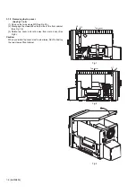
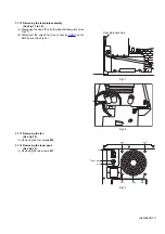
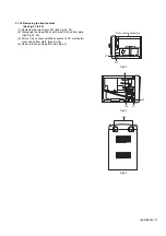
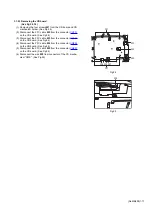
3.1.12 Removing the rear plate assembly
(See Fig.17 to 18)
(1) Disengage the claws
I1
on both sides of bottom plate. (See
Fig.17)
(2) Disconnect the wire
I2
from the connector
CN105
on the
AMP board. (See Fig.18)
Fig.17
Fig.18
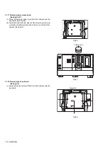
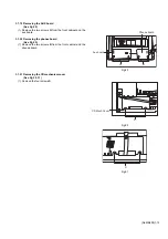
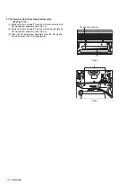
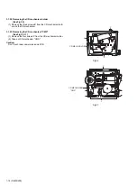
3.1.13 Removing the fan
(See Fig.19)
(1) Removing the four screws
M2
.
3.1.14 Removing the tuner pack
(See Fig.19)
(1) Removing the two screws
M1
.
Fig.19
I1
Rear plate assembly
I2
m1
m2
m2
Fan
m2
m2
m1
Tuner pack
Summary of Contents for UX-S59
Page 38: ...2 1 Block diagram ...
Page 39: ...2 2 Standard schematic diagrams Amp section ...
Page 40: ...2 3 Micon section ...
Page 41: ...2 4 CD section ...

