background image

1-32 (No.MB211)

SECTION 4

ADJUSTMENT

This service manual does not describe ADJUSTMENT.

Summary of Contents for UX-S57

Page 1: ...O COMPONENT SYSTEM MB211 2004 5 UX S57 TABLE OF CONTENTS 1 PRECAUTION 1 3 2 SPECIFIC SERVICE INSTRUCTIONS 1 7 3 DISASSEMBLY 1 8 4 ADJUSTMENT 1 32 5 TROUBLESHOOTING 1 33 Area suffix A Australia B U K E Continental Europe EN Northern Europe EV Eastern Europe CA UXS57 SP UXS57 SP UXS57 ...

Page 2: ...D Capacity 5 CDs Dynamic range 87 dB Signal to noise ratio 90 dB Wow and flutter Immeasurable General Power requirement AC 230 V 50 Hz Power consumption 110 W at operation 17 W on standby 1 4 W in power save mode Dimensions W H D approx 175 mm 240 mm 378 mm Mass approx 7 4 kg Speaker Section SP UXS57 Type 2 way bass reflex type Speakers Woofer 12 cm cone 1 Tweeter 4 cm cone 1 Power handling capaci...

Page 3: ...ack control shafts etc to be sure the product is safe to operate without danger of electrical shock Do not use a line isolation transformer during this check Plug the AC line cord directly into the AC outlet Using a Leakage Current Tester measure the leakage current from each exposed metal parts of the cabinet particular ly any exposed metal part having a return path to the chassis to a known good...

Page 4: ...same safety characteristics as the recommended replacement parts shown in the Parts List of the Service Manual and may create shock fire or other hazards 4 The leads in the products are routed and dressed with ties clamps tubings barriers and the like to be separated from live parts high temperature parts moving parts and or sharp edges for the prevention of electric shock and fire hazard When ser...

Page 5: ...he optical pickup The tester s internal power source can easily destroy the laser diode 1 7 Handling the traverse unit optical pickup 1 Do not subject the traverse unit optical pickup to strong shocks as it is a sensitive complex unit 2 Cut off the shorted part of the flexible cable using nippers etc after replacing the optical pickup For specific details refer to the replacement procedure in the ...

Page 6: ...lock failed or defeated AVOID DIRECT EXPOSURE TO BEAM e VARNING Synlig och osynling laserstrålning när den öppnas och spärren är urkopplad Betrakta ej strålen s VARO Avattaessajasuojalukitus ohitettuna tai viallisena olet alttiina näkyvälle ja näkymättömälle lasersäteilylle Vältä säteen kohdistumista suoraan itseesi f ADVARSEL Synlig og usynlig laserstråling når maskinen er åben eller interlocken ...

Page 7: ... No MB211 1 7 SECTION 2 SPECIFIC SERVICE INSTRUCTIONS This service manual does not describe SPECIFIC SERVICE INSTRUCTIONS ...

Page 8: ... the six screws A attaching the metal cover See Fig 1 2 From the both sides of the main body remove the two screws B attaching the metal cover See Figs 2 and 3 3 Remove the metal cover in the direction of the arrow while extending the lower sections of the metal cover See Figs 2 and 3 Fig 1 Fig 2 Fig 3 A A A Metal cover B Metal cover B Metal cover ...

Page 9: ... 4 3 From the top side of the main body remove the screws C attaching the front panel assembly See Fig 5 4 From the bottom side of the main body remove the two screws D attaching the front panel assembly See Fig 6 5 Release the two claws a and claw b from the both and bot tom sides of the front panel assembly and remove the front panel assembly in the direction of the arrow See Fig 6 Reference Whe...

Page 10: ...tors CN103 on the power supply board toward this side 3 From the forward side of the power supply board discon nect the wires from the connectors CN100 to CN102 CN104 Reference When attaching the screw G attach the primary protector with it 3 1 5 Removing the tuner See Fig 8 Remove the metal cover 1 From the left side of the main body disconnect the card wire from the connector CN1 on the tuner 2 ...

Page 11: ...e forward side of the micon board disconnect the card wire from the connectors CN765 See Fig 10 Fig 9 Fig 10 3 1 7 Removing the power amplifier board See Fig 11 Remove the metal cover front panel assembly rear panel power supply board and micon board 1 From the top side of the main body remove the wire holder and tie band fixing the wire 1 2 Remove the four screws L attaching the power amplifier b...

Page 12: ...se side of the power amplifier board bend the claws i of the heat sink in the direction of the arrow See Fig 12 2 From the forward side of the power amplifier board remove the four screws M attaching the heat sink See Fig 13 3 Disengage the joints j and remove the heat sink in the di rection of the arrow See Fig 13 Fig 12 Fig 13 Power amplifier board i M Power amplifier board M Heat sink j ...

Page 13: ... 1 10 Removing the power transformer See Fig 15 Remove the metal cover front panel assembly rear panel power supply board micon board and power amplifier board 1 From the top side of the main body remove the wire hold ers fixing the wire 2 Remove the tie band 3 Remove the four screws P attaching the power transformer and take out the power transformer from the main body Reference After attaching t...

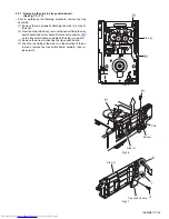
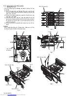
Page 14: ...of the main chassis in the holes of the CD bracket F See Fig 17 4 From the top side of the main body remove the two screws S attaching the CD changer mechanism assembly See Fig 18 Reference Align the projections n on the bottom chassis in the holes of the CD changer mechanism assembly before attach ing the screws S See Fig 18 5 Take out the CD changer mechanism assembly in the di rection of the ar...

Page 15: ...m the inside of the front panel assembly remove the screw U attaching the earth wire Reference When attaching the screw U attach the earth wire with it 2 Remove the four screws V attaching the front assembly section 3 Take out the front assembly section from the front panel assembly Fig 20 V V V V Front assembly section Front panel assembly U Earth wire ...

Page 16: ...e front assembly section remove the five screws W and screw W attaching the switch board See Fig 22 3 Disconnect the card wire from the connector CN510 on the switch board See Fig 22 Reference When attaching the screw W attach the earth wire with it See Fig 22 4 Take out the switch board from the front assembly section See Fig 22 Fig 21 Fig 22 Front assembly section Volume knob W W Front assembly ...

Page 17: ...e inside of the front assembly section remove the six screws X attaching the back light board 2 Take out the back light board from the front assembly sec tion and disconnect the card wires from the connectors CN551 CN552 on the back light board Fig 23 X X CN552 CN551 Front assembly section Back light board ...

Page 18: ... the front assembly section remove the four screws Y attaching the lens holder See Fig 24 2 Take out the lens holder with the LED lens and cover sheet See Fig 24 3 Take out the FL board from the front assembly section See Fig 25 Fig 24 Fig 25 Y Y Y Y Front assembly section Lens holder Cover sheet LED lens FL board Front assembly section ...

Page 19: ...ront panel assembly remove the screw Z attaching the headphone jack board 2 Take out the headphone jack board from the front panel as sembly Reference After attaching the headphone jack board fix the wire with the spacer as before Fig 26 Front panel assembly Z Spacer Headphone jack board Wire ...

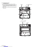
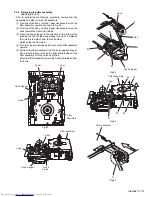
Page 20: ...the body to unlock the tray assembly Draw out the trays to ward the front Attention The tray can be locked if all tray assemblies are at tached 5 From top of the body move the stopper tab c in the direc tion of the arrow and release Pull out the tray assemblies from the body Caution Remove the tray assembly from top tray 5 in order Attention When reattaching the sub tray of the tray assembly or wh...

Page 21: ...gure 4 Disconnect the card wire from connector CN601 on the servo control board Caution Unsolder the short circuit point after reassembling Caution When reassembling twist the wires to be connected to con nector CN252 and CN253 twice 3 3 3 Removing the switch board See Fig 9 1 Disconnect the wires from connector CN252 and CN253 on the servo control board 2 Remove the screw C attaching the switch b...

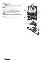
Page 22: ...hould remove the screws attaching the motor from top of the body Refer to another section 3 Remove the two screws E attaching the motor board 4 Remove the spacer fixing the motor board and tray switch board and disconnect connector CN2 on the motor board 5 Disconnect the card wire from connector CN1 on the motor board Caution When reconnecting the card wire let the card wire through the slot g of ...

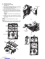
Page 23: ...oving the CD tramecha assembly See Fig 12 Prior to performing the following procedure remove the servo control board 1 Turn over the body and remove the three screws F attach ing the tramecha Fig 12 F CD Tramecha assembly F F ...

Page 24: ... in the direction of the arrow to move the pickup assembly outward 2 Push down the stopper h in the direction of the arrow and pull out the shaft 3 Release the joint i of the pickup assembly and mecha base 4 Remove the screw G attaching the CD rack Release the four tabs j at the bottom of the CD rack Fig 13 Fig 14 h i Pickup assembly Mecha base Shaft Shaft Shaft Cam gear Stopper Stopper CD lack Pi...

Page 25: ...e of the body remove the spacer fixing the tray switch board and motor board Disconnect connector CN3 on the tray switch board and detach the side L upward 3 Remove the screw J attaching the tray switch board 4 Push the joint tab k of the side L in the direction of the ar row and remove the tray switch board outward then re lease joint l Fig 15 Fig 16 Fig 17 H H Side L CN3 Spacer Side L H H k l J ...

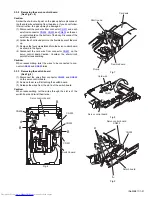
Page 26: ...y 3 From top of the body turn the 1 gear clockwise to move the elevator cam rearward Move the two slots o and joint p of the elevator cam as shown in Fig 21 and remove the ele vator cam outward 4 Remove the three screws K and detach the side R up ward Caution When reattaching the side R assembly make sure to fit the shaft part q into the slot of the select lever Fig 18 Fig 19 Fig 20 Fig 21 Fig 22 ...

Page 27: ...ab r of the hook stopper to unlock it Release four joints s to detach from the rack holder Release the rod from part t 4 Turn the 1 gear clockwise again to move the lifter assembly upward 5 Remove the lifter assembly from the body upward at posi tion u where the four pins on the right and left sides of the lifter assembly fit to the notches of the v Move the lifter assembly toward the front and re...

Page 28: ...e the spring attached to the bottom of the sensor as sembly from the boss z on the sensor slider 5 Remove the screw N and O attaching the sensor board and SV resister respectively If necessary unsolder the sensor board Caution When reattaching the SV resister attach the sensor slider to the sensor bracket and fit the lever on the bottom of the SV re sister into slot a of the sensor slider Caution ...

Page 29: ...g 30 Fig 31 Fig 32 Fig 33 M M z x y Spring Sensor assembly Spring Sensor slider a b z N O a Soldering point Sensor board SV resister Sensor braket Sensor slider c b z y M Sensor assembly Slide gear Spring Slide lever M ...

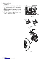
Page 30: ...ove the two belts on top of the body 2 Remove the four screws N attaching the motor 3 Remove the motor board from the bottom of the body Refer to the section Removing the motor board Attention When removing the motor board with the motor you need not to unsolder four soldered parts Caution When reattaching the motor turn the side where the label should be put to the front side Fig 34 Fig 35 Motor ...

Page 31: ...r clockwise to move the sub tray remaining inside the lifter assembly toward the front then pull out 5 Take out the CD on the sub tray 6 After clearing away the CD insert the sub tray into the main tray Caution When reattaching the sub tray move the tray stopper on the bottom of the main tray in the direction of the arrow to lock the sub tray certainly 7 Push the tray assembly toward the body and ...

Page 32: ...1 32 No MB211 SECTION 4 ADJUSTMENT This service manual does not describe ADJUSTMENT ...

Page 33: ... No MB211 1 33 SECTION 5 TROUBLESHOOTING This service manual does not describe TROUBLESHOOTING ...

Page 34: ... No MB211 AV MULTIMEDIA COMPANY AUDIO VIDEO SYSTEMS CATEGORY 10 1 1chome Ohwatari machi Maebashi city 371 8543 Japan VICTOR COMPANY OF JAPAN LIMITED WPC Printed in Japan ...

Reviews: