1-8 (No.MB595)
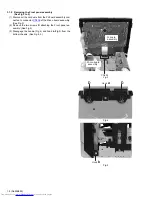
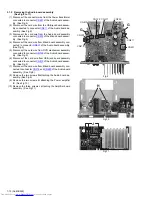
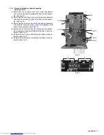
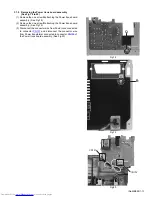
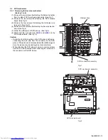
3.1.2 Removing the Front panel assembly
(See Fig.3 to 5)
(1) Disconnect the card wire from the FL board assembly con-
nected to connector
CN205
of the Micon board assembly.
(See Fig.3)
(2) Remove the two screws
D
attaching the Front panel as-
sembly. (See Fig.4)
(3) Disengage the hook
a
(Fig.4) and hook
b
(Fig.5) from the
bottom chassis. (See Fig.4, 5)
Fig.3
Fig.4
Fig.5
CN205
FL board
assembly
Micon board
assembly
Hook
a
D
D
Hook
b
Summary of Contents for UX-G68E
Page 37: ... M E M O ...


