


(No.MB595)1-19
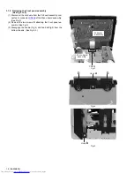
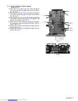
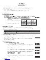
3.2.5 Removing the tray assembly
(See Fig.14 & 15)
(1) Remove the two screws
J
attaching the clamper base.
(See Fig.14)
(2) Remove the one screw
K
attaching the shaft guide from
bottom side. (See Fig.14)
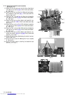
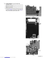
(3) Remove the two screws
L
attaching the shaft guide from
top side. (See Fig.15)
Caution:
When attach the tray assembly, boss of loading sub assembly
should attach to guide of bottom side at tray assembly. (See
Fig.15)
Fig.14
Fig.15
J
order 1
order 2
clamper base
K
[bottom side]
L
Summary of Contents for UX-G68E
Page 37: ... M E M O ...


