background image

12

7

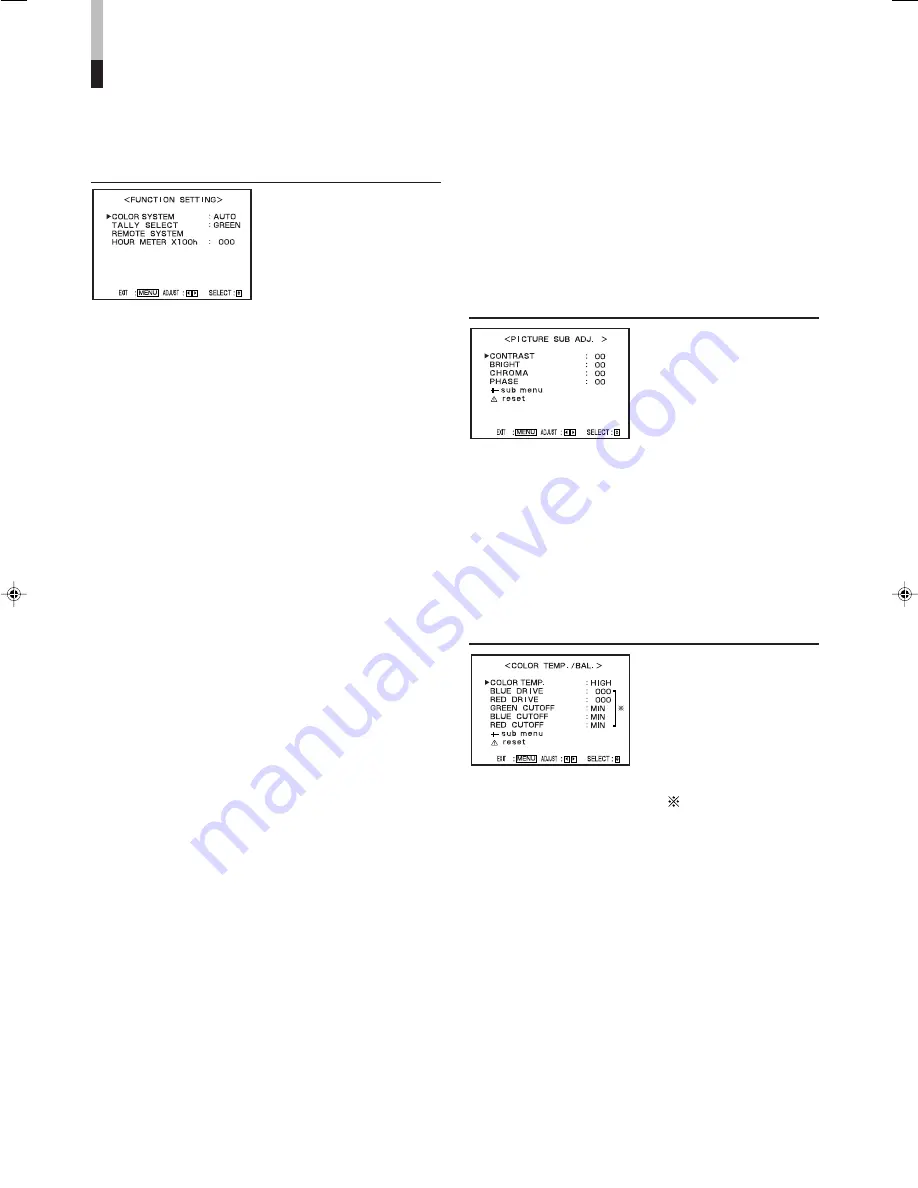
HOUR METER X100h

Displays the total usage time of the monitor in
hundred-hour units.

• 000 

O

 655

NOTES:

• When the timer passes 655, it returns to 000.
• The timer does not count usage time under one hour.

PICTURE SUB ADJ.

The standard value (“00”) of
the picture adjustment is
initially set at the factory.
You can adjust the standard
value as you want.

7

CONTRAST
• –20 

O

 00 

O

 +20

7

BRIGHT
• –20 

O

 00 

O

 +20

7

CHROMA
• –20 

O

 00 

O

 +20

7

PHASE
• –20 

O

 00 

O

 +20

COLOR TEMP./BAL.

Sets or adjusts the color
temperature and white
balance.

NOTE:

• Use the five items indicated with 

 mark to make fine

adjustments between the monitors.

7

COLOR TEMP.

Selects the color temperature.

HIGH:

Sets the color temperature to 9300.

LOW:

Sets the color temperature to 6500.

7

BLUE DRIVE

Adjusts the blue drive level.

• MIN 

O

 000 

O

 MAX (in 127 grades)

7

RED DRIVE

Adjusts the red drive level.

• MIN 

O

 000 

O

 MAX (in 127 grades)

7

GREEN CUTOFF

Adjusts the green cut-off point.

• MIN 

O

 MAX (in 155 grades)

How to Use SET-UP MENU 

(cont.)

7

Functions and Adjustment Range of Items

FUNCTION SETTING

Sets the control systems for
the COLOR SYSTEM,
colors of the tally lamp, and
MAKE/TRIGGER terminal.
• Can be also used to check

the amount of time that the
monitor has been used.

7

COLOR SYSTEM

Selects the color system.

AUTO:

Changes NTSC and PAL automatically.

NTSC:

Keeps the color system NTSC.

PAL:

Keeps the color system PAL.

NOTE:

• Normally select “AUTO.” However, if the input signal is

unstable, select “NTSC” or “PAL.”

7

TALLY SELECT

Selects the color of the tally lamp on the upper right
of the front panel.

GREEN:

The tally lamp lights in green.

RED:

The tally lamp lights in red.

NOTES:

• “TALLY SELECT” does not appear on the menu when

both of the following conditions are applied:
– When selecting “TA. SEL” to a pin terminal of the

MAKE/TRIGGER terminal in “REMOTE SYSTEM” of
SET-UP MENU.

– When the external control is activated.

• The tally lamp is controlled using the MAKE/TRIGGER

terminal of the REMOTE (external control) terminals.

“REMOTE SYSTEM” below, “How to Use the External
Control” on pages 14 and 15

7

REMOTE SYSTEM

Sets the MAKE/TRIGGER terminal.

“How to Use the MAKE/TRIGGER Terminal” on pages
14 and 15

• CONTROL FORM:

Selects the control system for the MAKE/
TRIGGER terminal.

MAKE:

Selects the make contact system as
the external control method.

TRIG.:

Selects the trigger system as the
external control method.

SET:

You can apply the functions to the 1st
to 6th pin terminals of the MAKE/
TRIGGER terminal as you want.

• PORT F1 – PORT F6:

Selects the function to be applied to the 1st to 6th
pin terminals of the MAKE/TRIGGER terminal.

“How to Use the MAKE/TRIGGER Terminal” on page 14

NOTE:

• You can set “PORT F1” – “PORT F6” only when

“CONTROL FORM” is set to “SET.”

En_11-20_TM-1011G.p65

06.2.14, 22:37

12

Summary of Contents for TM-1011

Page 1: ...INSTRUCTIONS TM 1011G LCT1989 001A H COLOR VIDEO MONITOR ...

Page 2: ...er 120 V 220 240 V 50 Hz 60 Hz DC power 12 V Keep flammable material water and metal objects away from the unit especially the interior of the unit This unit incorporates high voltage circuitry For your own safety and that of your equipment do not attempt to modify or disassemble this monitor There are no user serviceable parts inside 7 SCREEN BURN It is not recommended to keep a certain still ima...

Page 3: ...or AC 120 V as for AC 220 240 V Doing so may cause malfunction electric shock or fire Note for the United Kingdom power cord only The plug on the United Kingdom power cord has a built in fuse When replacing the fuse be sure to use only a correctly rated approved type re fit the fuse cover Consult your dealer or qualified service personnel How to replace the fuse Open the fuse compartment with a bl...

Page 4: ...not adjustable when the PAL signal or the B W 50 Hz 60 Hz signal is input 3 CONTRAST BRIGHT button Activates the picture contrast adjustment mode or picture brightness adjustment mode Each time you press the button the adjustment modes change To adjust the value move the MENU VOLUME control 4 to 4 MENU VOLUME control Adjusts the volume level by moving the control to Displays or closes a menu scree...

Page 5: ...by mode Green The monitor is on q Stand by button Turns on and off the monitor when the AC or DC switch on the rear panel is on NOTE When using the DC power supply turning on the DC switch on the rear panel puts the monitor in stand by mode To turn on the monitor press the stand by button 7 About the status display Displays information of the current input selection and the monitor settings for ab...

Page 6: ...he DC power supply 12 V NOTES Regarding the DC power supply consult with your dealer While connecting both the AC and DC power supply AC power supply is preferentially used If the AC power supply is cut off for example when unplugging the AC power cord the power supply automatically switches to the DC power supply Controls and Features cont w e u r t y 1 2 4 3 Pin terminals of the DC IN 12 V conne...

Page 7: ...for the analog audio signals NOTE The IN and OUT terminals are bridge connected y REMOTE external control terminals Terminals for controlling the monitor by an external control How to Use the External Control on pages 14 and 15 u DC switch Turns the DC power on and off I on 䡬 off NOTES You need to turn on the stand by button on the front panel to turn on the monitor after turning on the DC switch ...

Page 8: ...POSI ADJ Adjusts the size and position of the picture DISTORTION ADJ Compensates the picture distortion Also compensates the picture tilt which is caused by geomagnetic influence STATUS DISPLAY Sets the item related to turning on off the status display CONTROL LOCK Prohibits altering the monitor operations except turning the monitor on off and deactivating this function Operating the monitor by th...

Page 9: ...reen 7About reset Restores all menu settings currently displayed to factory preset values 1 Move the MENU VOLUME control to to select reset then move it to Confirmation message is displayed 2 To initialize move the MENU VOLUME control to To cancel the initialization push in the MENU VOLUME control NOTE This function is only available when reset is displayed in the menu 7Displaying the Menu Screens...

Page 10: ...7Functions and Adjustment Range of Items see below APERTURE CONTROL Compensates the frequency characteristics of the luminance signal of a video signal 7 LEVEL Adjusts the compensation value The higher the number is the larger the compensation value gets 00 O 10 7 CONTROL FREQ Selects the frequency to compensate HIGH Compensates the high frequencies LOW Compensates the low frequencies OFF No compe...

Page 11: ...to page 13 To go back to the previous menu press the MENU VOLUME control NOTE Some items do not appear on the menu depending on the signal currently input or if there is no signal input Those items are not available to use Move the MENU VOLUME control to to adjust an item About sub menu and reset page 9 ...

Page 12: ...he color system AUTO Changes NTSC and PAL automatically NTSC Keeps the color system NTSC PAL Keeps the color system PAL NOTE Normally select AUTO However if the input signal is unstable select NTSC or PAL 7 TALLY SELECT Selects the color of the tally lamp on the upper right of the front panel GREEN The tally lamp lights in green RED The tally lamp lights in red NOTES TALLY SELECT does not appear o...

Page 13: ...right and the lower side to the left Moves the upper side of the picture to the left and the lower side to the right 7 TRAPEZOID Compensates the trapezoid picture distortion 20 O 00 O 20 Enlarges the upper side of the picture Reduces the upper side of the picture 7 ROTATION Compensates a picture tilt 31 O 00 O 31 Turns the picture clockwise Turns the picture counterclockwise STATUS DISPLAY Sets th...

Page 14: ...em you can also use those functions operating the monitor directly 7How to Use the MAKE TRIGGER Terminal 7 Function of the MAKE TRIGGER terminal The following are the configurations and the functions of the pin terminals of the RJ 45 connector You can change the functions applied to the 1st to 6th pin terminals by setting REMOTE SYSTEM of SET UP MENU Caution This is a female connector 7 To change ...

Page 15: ... opening it When selecting the TRIG trigger system operate each function by Pulse control that is short circuiting the corresponding pin terminal to the 8th pin terminal GND for about 1 second NOTES When controlling INP A or INP B only one terminal must be short circuited Other terminals must be opened When selecting the TRIG trigger system you can operate only one function at a time Operate the f...

Page 16: ... 6 7 5 18 17 4 6 7 4 12 12 13 5 4 12 Problems No power supply No picture with the power on No sound with the power on Wrong color Unnatural picture Shaking picture Irregular color Points to be checked Is the AC or DC power plug loose or disconnected When using the DC power supply is the battery charged Is the AC or DC switch turned off Is the signal cable disconnected Is the power of the connected...

Page 17: ...he CRT and is not harmful The monitor emits a strange sound when the room temperature changes suddenly This is only a problem if an abnormality appears on the screen as well If two or more monitors are placed close each other their images may shake or be distorted This phenomenon is due to mutual interference it is not a malfunction Move the monitors away from each other until the interference dis...

Page 18: ... PAL 4 43 MHz B W 50 Hz 60 Hz Operating temperature 0 C 40 C 32 F 104 F Operating humidity 20 80 non condensing AC power 120 V 220 240 V 50 Hz 60 Hz DC power 12 V 0 9 A AC 120 V 0 6 A AC 220 240 V 4 3 A DC 12 V Width 222 mm 8 3 4 Height 229 mm 9 1 8 Depth 338 3 mm 13 3 8 7 8 kg 17 2 lbs AC power cord Specifications Model Type Picture Tube Effective Screen Size Scanning Frequency Video Band Horizon...

Page 19: ... Unit mm inch Front View Side View Asterisks are used to indicate front panel dimensions 222 8 3 4 183 7 1 4 140 5 5 8 164 6 1 2 222 8 3 4 63 5 2 1 2 7 3 8 7 3 8 307 8 12 1 8 1 5 1 16 338 3 13 3 8 220 8 3 4 229 9 1 8 ...

Page 20: ... 2006 Victor Company of Japan Limited 0306STH MW MT TM 1011G COLOR VIDEO MONITOR ...

Reviews: