


1-8 (No.82996)
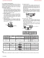
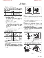
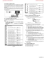
Fig.3-1d
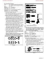
2. FFC WIRE and DRUM FPC WIRE should be insert as follows.
1. Insert direction of FCC WIRE as follows.
right side
electrode side
3.Insert the wire to even the root of connector completely
at the same time as inserting each wire.
CN
OK
90
supporting side
CN
CN
NG
back side
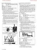
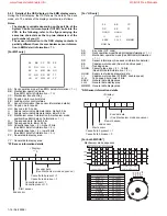
NOTE
For the prevention of the DRUM FPC damage.
When you attach the MECHA UNIT on B.CHASSIS.
Attach the MECHA UNIT after the positioning boss "Z" of the
B.CHASSIS is matched to the positioning hole of MECHA UNIT.
J3001
(WR3a)
<Note 3a>
(WR2a)
<Note 3a>
(WR3b)
<Note 3a>
(L4a)
(L4a)
Hang the hook of CHASSIS on the PWB.
Hang the hook of CHASSIS on the PWB.
CN2001
WHITE LINE
CN7001
Cable box/remote pause board assembly
2
FW3001
CN7003
BOTTOM SIDE
TOP SIDE
(WR2a)
<Note 3a>
Adv. jog board assembly
Accord the position of V gap on R. Encoder and PWB silk " ".
Accord the position of Boss on R. Encoder and PWB silk " ".
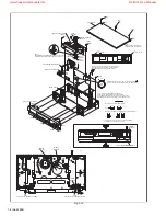
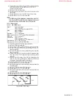
[2] Front panel assembly
<Note 2a>
Bottom chassis
(L2a)
(L2c)
(L2a)
(L2b)
(L2b)
(L2b)
z
JS
30
01
Q3001
FW
30
01
Q3
00
2
D3
00
1
b
b
a
z
c
c
Must confirm soldering condition as no soldering and
dry soldering at portion of Power cord lead on Main
pwb before attach Main pcb to Bottom chassis.
a
d
NOTE)
CONFIRM THE DOOR OPENER IS DOWN.ATTACH THE
F.PANEL AFTER THE CASSETE DOOR IS LIFTED UP.
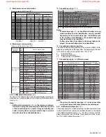
[3] Drum assembly
<Note 3d>
(S2a)
(S3a)
<Note 3b>
(S3d)
<Note 3d>
(S3e)
<Note 3d>
(S2a)
(S4a)
(S3c)
<Note 3d>
(S3b)
<Note 3b>
[3] Mechanism assembly
<Note 3c>
[4] Main board assembly
3D digital/2M board assembly
WHITE LINE
VA5001
C5001
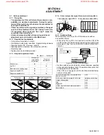
NOTE)
HANG THE HOOK OF THE TOP
COVER IN HOLD OF CHASSIS.
[1]Top cover
(S1)
(S1)
(S1)
(L1)
(L1)
(L4b)
(L4c)
PAUSE /
AV COMPULINK
CABLE BOX
003
ANT. IN
TV OUT
AUDIO
VIDEO
R
L
IN
OUT
(L1)
Push to release.
(L1)
Push to release.
www.freeservicemanuals.info
World of Free Manuals


