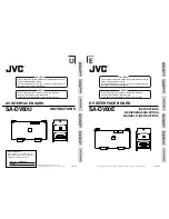


(U-4)
2. System Configuration, Connections
System Configuration and Connection Examples for different Applications
A system for digital editing and/or dubbing can be configured and connected by referring to the
following examples according to the available units and the required function.
䡵
Operate the connected units correctly by referring to their instruction manuals.
䡵
Cables for connection between units are not provided.
Please purchase the applicable connector cables as required.
䡵
DV connection target models
GY-DV500U *
2
GY-DV550U
GY-DV700WU
BR-DV600U *
2
BR-DV600UA
DV nonlinear editor *
1
*1. For the DV nonlinear editors, please consult your nearest JVC dealer.
*2. Precautions for connection of the GY-DV500U or BR-DV600U
(1) Time codes cannot be dubbed.
(2) When the DV device is switched from the Still mode to the Play mode, audio may be
interrupted momentarily. This is not a malfunction.
(3) Sets having serial numbers other than those shown below cannot be connected to this
unit. For information concerning their upgrade versions, please consult your local JVC-
authorized service agent.
AC IN 120V
50 / 60Hz
VIDEO OUT
REF
VIDEO IN
Y
LINE
R-Y
B-Y
Y/C 358
Y
R-Y
B-Y
Y/C 358
LINE-2
LINE-1
VIDEO
AUDIO
MONITOR OUT
TIME CODE
ON
OFF
75
Ω
DIAGNOSTIC
REMOTE (9P)
VIDEO CONTROL
AUD-1
AUD-2
AUD-1
AUD-2
AUDIO IN
AUDIO OUT
LEVEL
- 6dB
+ 4dB
LEVEL
- 6dB
+ 4dB
IN
OUT
DV IN/OUT
VTR CTRL
POWER
ON
OFF
H
M
F
S
COUNTER
CTL
TC
UB
REMOTE
LOCAL
9PIN
AUDIO
MONITOR
AUDIO
INPUT
VIDEO
INPUT
DA1
MIX
DA2
DIG
LINE
Y/C
(CPN)
DIG
ANA
REC
PLAY
PAUSE / STILL
REW
STOP
FF
EJECT
SEARCH
PHONES
LEVEL
AUDIO REC LEVEL
DA-2
DA-1
TRACKING
SERVO
VIDEO1
VIDEO2
USER
OTHERS
ON SCREEN
TIME CODE
SYSTEM
STAND BY
TIME CODE
VIDEO CONTROL
MENU
SET
SELECT
METER MODE
FINE
TRACKING
TIME CODE GEN.
SET
HOLD
COUNTER
RESET
SYSTEM
PHASE
SC
PHASE
VIDEO
PHASE
INT
REC PRESET
REGEN
FREE
EXT
CHANNEL
CONDITION
CTL
SERVO
AUTO OFF
DF
EMP
JOG
GEN
VIDEO CASSETTE RECORDER
BR-D80U
OVER
OVER
-
15
-
16
-
17
-
18
-
19
-
20
-
21
-
22
-
23
-
24
0
-
4
-
8
-
12
-
16
-
20
-
25
-
30
-
40
-
60
-
15
-
16
-
17
-
18
-
19
-
20
-
21
-
22
-
23
-
24
0
-
4
-
8
-
12
-
16
-
20
-
30
-
40
-
60
-
25
STILL
X-1
REV
FWD
X1
DA2/TRACKING
DA1
P.READ
LIGHT
ON
OFF
COUNTER
CTL
TC
UB
RESET
OPERATE/WARNING
MONITOR
SELECT
STATUS
SHUTTER
MENU
FILTER
1 3200k
2 5600k
3 5600k+ND
POWER
NG
GAIN
OUTPUT
WHT.BAL
VTR
ON
OFF
ALARM
MONITOR
S
A
V
E
S
T
B
Y
H
M
L
B
A
R
S
C
A
M
A
U
T
O
K
N
E
E
P
R
S
T
A
B
O
N
O
F
F
CH-1
CH-2
AUDIO
LEVEL
AUTO IRIS
LOLUX
BACK L
NORMAL
SPOT L
STRETCH
NORMAL
COMPRESS
FULL AUTO BLACK
V.IN/A.MONI A.OUT
COUNTER
DV
CTL
TC
UB
CH-1/2
CH-3/4
Y/C
(CPN)
LINE
L
R
MIX
MIX
PHONES
MIC
REMOTE
LOCAL
EJECT
OPERATE
REC LEVEL
CH-2/4
CH-1/3
SHIFT
SET
SELECT
SHIFT
MENU
HOLD
SHIFT
A. DUB
ADVANCE PRESET
REW
STOP
FF
REC
PLAY
PAUSE
ON/OFF
MENU
OVER
OVER
H
M
S
F
AUD LOCK
SP
32k
48k
SLAVE
PB
NDF
SERVO RF
DEW
AUTO OFF
HOLD
CH 2/4
CH 1/3
VIDEO CASSETTE RECORDER BR-DV600UA
dB
40 30
20
10
0
L A P
I N
O U T
S E R V O
L A P
I N
O U T
S E R V O
LAP
RESET
LAP
RESET
TOTAL
RECORDER
EJECT
PLAYER
EJECT
P
AUX
CONTINUE
START
END
V.SPEED
EVENT
RENUMBER
RIPPLE
MAN.TAKE
LEARN
MENU
REC
REW
FF
STOP
STB OFF
SEARCH
PAUSE
/STILL
PLAY
REC
REW
FF
STOP
STB OFF
SEARCH
PAUSE
/STILL
PLAY
ASSEM
VIDEO
AUD-1
AUD-2
SPLIT
TC
SPLIT
CANCEL
LAST
ED
REC
EE
OUT
IN
OUT
IN
ENTRY
PREVIEW
AUTO EDIT
GOTO
REVIEW
SHIFT
ALL STOP
MAX
MIN
MONITOR
MAX
MIN
MONITOR
FWD
REV
STILL
X-1
X1
FWD
REV
STILL
X-1
X1
R E C O R D E R
P L A Y E R
HOUR
MIN
SEC
FRAME
HOUR
MIN
SEC
FRAME
P
R
VITC
LTC
CTL
VITC
LTC
CTL
BUMP
PREROLL
7
5
3
ON
OFF
EVENT No.
V.SPEED
A.SPLIT
DURATION
IN
OUT
IN
OUT
E D I T I N G C O N T R O L U N I T
R M — G 8 2 0 U
+
–
Mini DV
(VIDEO/AUDIO)
DV cable (4P-4P)
Mini DV
tape
DV recorder
BR-DV600UA
Player
Editing control unit RM-G820U
D9 editing recorder BR-D80U
DV camcorder GY-DV500U
Front panel
Rear panel
DV connector
DV connector
SA-DV60U
VCR CONTROL
not connected
REMOTE(9P)
REMOTE(9P)
VIDEO OUT
SYNC
IN
9P-9P remote cable
9P-9P remote cable
Recorder
• For data bump, select the recorder
device and use its Learning function.
• The pre-roll time should be set to
more than 5 seconds.
Model Name
Last 5 digits of S/No.
GY-DV500U
xxx16552 and after
xxx56552 and after
xxx31501 and after
Model Name
Last 5 digits of S/No.
BR-DV600U
xxx12040 and after
xxx52040 and after
(1) DV D9 linear editing system
The editing precision of the player device of the system described below is +1( ) frame.
+1
–0
(E-6)
AC IN 120V
50 / 60Hz
VIDEO OUT
REF
VIDEO IN
Y
LINE
R-Y
B-Y
Y/C 358
Y
R-Y
B-Y
Y/C 358
LINE-2
LINE-1
VIDEO
AUDIO
MONITOR OUT
TIME CODE
ON
OFF
75
Ω
DIAGNOSTIC
REMOTE (9P)
VIDEO CONTROL
AUD-1
AUD-2
AUD-1
AUD-2
AUDIO IN
AUDIO OUT
LEVEL
- 6dB
+ 4dB
LEVEL
- 6dB
+ 4dB
IN
OUT
DV IN/OUT
VTR CTRL
POWER
ON
OFF
H
M
F
S
COUNTER
CTL
TC
UB
REMOTE
LOCAL
9PIN
AUDIO
MONITOR
AUDIO
INPUT
VIDEO
INPUT
DA1
MIX
DA2
DIG
LINE
Y/C
(CPN)
DIG
ANA
REC
PLAY
PAUSE / STILL
REW
STOP
FF
EJECT
SEARCH
PHONES
LEVEL
AUDIO REC LEVEL
DA-2
DA-1
TRACKING
SERVO
VIDEO1
VIDEO2
USER
OTHERS
ON SCREEN
TIME CODE
SYSTEM
STAND BY
TIME CODE
VIDEO CONTROL
MENU
SET
SELECT
METER MODE
FINE
TRACKING
TIME CODE GEN.
SET
HOLD
COUNTER
RESET
SYSTEM
PHASE
SC
PHASE
VIDEO
PHASE
INT
REC PRESET
REGEN
FREE
EXT
CHANNEL
CONDITION
CTL
SERVO
AUTO OFF
DF
EMP
JOG
GEN
VIDEO CASSETTE RECORDER
BR-D80U
OVER
OVER
-
15
-
16
-
17
-
18
-
19
-
20
-
21
-
22
-
23
-
24
0
-
4
-
8
-
12
-
16
-
20
-
25
-
30
-
40
-
60
-
15
-
16
-
17
-
18
-
19
-
20
-
21
-
22
-
23
-
24
0
-
4
-
8
-
12
-
16
-
20
-
30
-
40
-
60
-
25
STILL
X-1
REV
FWD
X1
DA2/TRACKING
DA1
P.READ
LIGHT
ON
OFF
COUNTER
CTL
TC
UB
RESET
OPERATE/WARNING
MONITOR
SELECT
STATUS
SHUTTER
MENU
FILTER
1 3200k
2 5600k
3 5600k+ND
POWER
NG
GAIN
OUTPUT
WHT.BAL
VTR
ON
OFF
ALARM
MONITOR
S
A
V
E
S
T
B
Y
H
M
L
B
A
R
S
C
A
M
A
U
T
O
K
N
E
E
P
R
S
T
A
B
O
N
O
F
F
CH-1
CH-2
AUDIO
LEVEL
AUTO IRIS
LOLUX
BACK L
NORMAL
SPOT L
STRETCH
NORMAL
COMPRESS
FULL AUTO BLACK
V.IN/A.MONI A.OUT
COUNTER
DV
CTL
TC
UB
CH-1/2
CH-3/4
Y/C
(CPN)
LINE
L
R
MIX
MIX
PHONES
MIC
REMOTE
LOCAL
EJECT
OPERATE
REC LEVEL
CH-2/4
CH-1/3
SHIFT
SET
SELECT
SHIFT
MENU
HOLD
SHIFT
A. DUB
ADVANCE PRESET
REW
STOP
FF
REC
PLAY
PAUSE
ON/OFF
MENU
OVER
OVER
H
M
S
F
AUD LOCK
SP
32k
48k
SLAVE
PB
NDF
SERVO RF
DEW
AUTO OFF
HOLD
CH 2/4
CH 1/3
VIDEO CASSETTE RECORDER BR-DV600UA
dB
40 30
20
10
0
L A P
I N
O U T
S E R V O
L A P
I N
O U T
S E R V O
LAP
RESET
LAP
RESET
TOTAL
RECORDER
EJECT
PLAYER
EJECT
P
AUX
CONTINUE
START
END
V.SPEED
EVENT
RENUMBER
RIPPLE
MAN.TAKE
LEARN
MENU
REC
REW
FF
STOP
STB OFF
SEARCH
PAUSE
/STILL
PLAY
REC
REW
FF
STOP
STB OFF
SEARCH
PAUSE
/STILL
PLAY
ASSEM
VIDEO
AUD-1
AUD-2
SPLIT
TC
SPLIT
CANCEL
LAST
ED
REC
EE
OUT
IN
OUT
IN
ENTRY
PREVIEW
AUTO EDIT
GOTO
REVIEW
SHIFT
ALL STOP
MAX
MIN
MONITOR
MAX
MIN
MONITOR
FWD
REV
STILL
X-1
X1
FWD
REV
STILL
X-1
X1
R E C O R D E R
P L A Y E R
HOUR
MIN
SEC
FRAME
HOUR
MIN
SEC
FRAME
P
R
VITC
LTC
CTL
VITC
LTC
CTL
BUMP
PREROLL
7
5
3
ON
OFF
EVENT No.
V.SPEED
A.SPLIT
DURATION
IN
OUT
IN
OUT
E D I T I N G C O N T R O L U N I T
R M — G 8 2 0 U
+
–
Mini DV
(VIDEO/AUDIO)
DV cable (4P-4P)
Mini DV
tape
DV recorder
BR-DV600EA
Player
Editing control unit RM-G820E
D9 editing recorder BR-D80E
DV camcorder GY-DV500E
(1) DV D9 linear editing system
Front panel
Rear panel
DV connector
DV connector
SA-DV60E
VCR CONTROL
not connected
REMOTE(9P)
REMOTE(9P)
VIDEO OUT
SYNC
IN
9P-9P remote cable
9P-9P remote cable
Recorder
• For data bump, select the recorder
device and use its Learning function.
• The pre-roll time should be set to
more than 5 seconds.
The editing precision of the player device of the system described below is +1 frame.
+1
–0
( )
2. System Configuration, Connections (continued)
E
U