background image

28

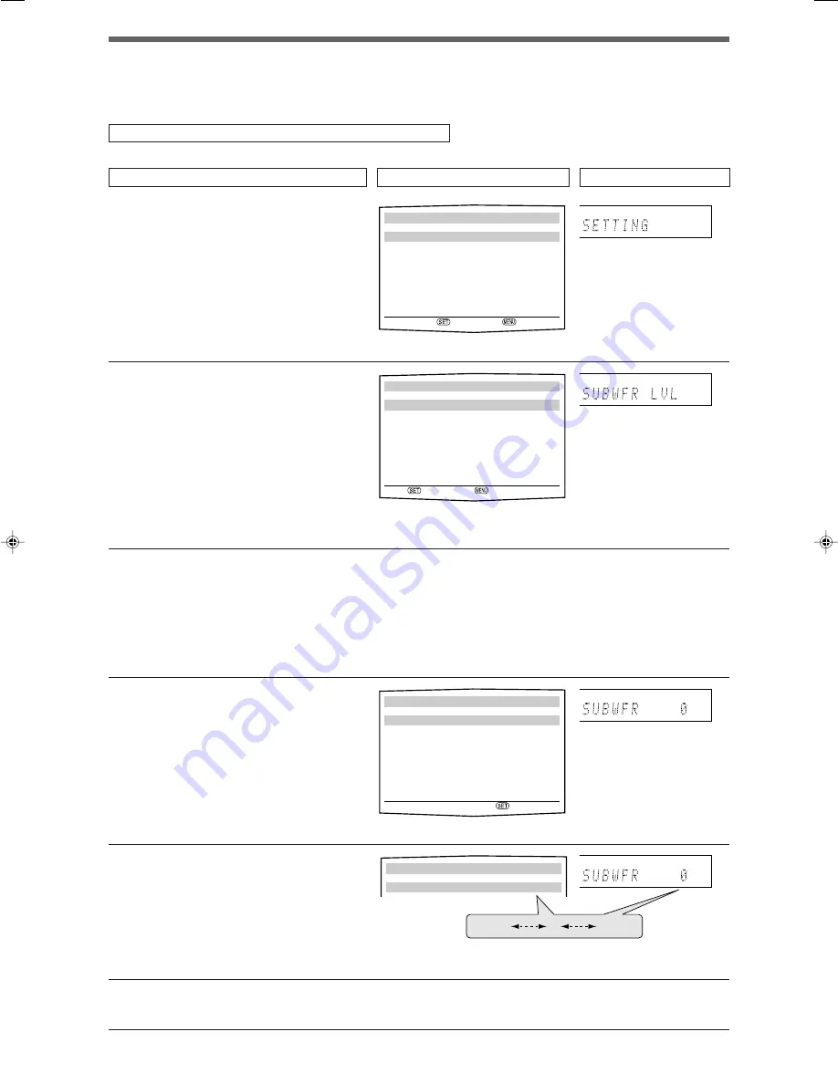
Ex.: When adjusting subwoofer output level.

1

To show “TOP MENU,” press MENU.
Then press 

5

 or 

 to select “ADJUST

MENU.”

• On the front panel, turn MULTI JOG.

2

To select “ADJUST MENU,” press SET.

3

To select the desired submenu, press

5

 or 

 repeatedly.

There are three screens from “ADJUST MENU (1)”
to “ADJUST MENU (3).” To change the screen,
simply pressing 

5

 or 

 repeatedly. You can go to

the next/previous screen.

• On the front panel, turn MULTI JOG.

4

Press SET.

5

To adjust the selected item, press 

2

 or

3

 repeatedly, then press SET.

The on-screen display returns to the previous
ADJUST MENU. In this example, “ADJUST MENU
(1)” appears on the TV screen and “SUBWFR LVL”
appears on the display.

• On the front panel, turn MULTI JOG, then press

SET.

6

Repeat steps 

2

 to 

5

 to set other items

if necessary.

The adjustment item previously selected
appears.

The submenu previously
selected appears.

The selected submenu appears.

The current setting of the
selected item appears.

Menu operating procedure

When operating, the on-screen display appears on the TV screen regardless of the SUPERIMPOSE setting (see page 25).

Before you start, remember...

There is a time limit in doing the following steps. If the setting is canceled before you finish, start from step 

again.

In this section, the operation of the remote control is used for explaining.

Operations

On the TV screen

On the display

“SETTING” appears.

“TOP MENU” appears.

x

O P. BASS

TA NEWS INFO RDS TUNED ST

SLEEP

AUTO MUTING

AUTO MODE

ATT
HP
MHz

kHz

x

O P. BASS

TA NEWS INFO RDS TUNED ST

SLEEP

AUTO MUTING

AUTO MODE

ATT
HP
MHz

kHz

x

O P. BASS

TA NEWS INFO RDS TUNED ST

SLEEP

AUTO MUTING

AUTO MODE

ATT
HP
MHz

kHz

x

O P. BASS

TA NEWS INFO RDS TUNED ST

SLEEP

AUTO MUTING

AUTO MODE

ATT
HP
MHz

kHz

 SUBWOOFER LEVEL 
 
 SUBWOOFER     :

2

   0 

3


23

:OPERATE    :BACK

 SUBWOOFER LEVEL 
 
 SUBWOOFER     :

2

   0 

3

–10

0

+10

 TOP MENU
 

5

 SETTING MENU
 ADJUST  MENU
 

         :ENTER   :EXIT

 ADJUST MENU (1)
 

5

 SUBWOOFER LEVEL  :   0 
 FRONT L LEVEL    :   0
 FRONT R LEVEL    :   0
 CENTER LEVEL     :   0
 SURR. L LEVEL    :   0
 SURR. R LEVEL    :   0
 SURR. BACK LEVEL :   0


     :ENTER   :TOP MENU

EN26-31RXF31S[UJ]1.p65

05.4.25, 15:47

28

Summary of Contents for RX-F31S

Page 1: ...English LVT1306 009B US RX F31S INSTRUCTIONS HOME CINEMA CONTROL CENTER ...

Page 2: ...es on the apparatus When discarding batteries environmental problems must be considered and local rules or laws governing the disposal of these batteries must be followed strictly Do not expose this apparatus to rain moisture dripping or splashing and that no objects filled with liquids such as vases shall be placed on the apparatus Caution Proper Ventilation To avoid risk of electric shock and fi...

Page 3: ... Midnight mode MIDNIGHT MODE 24 Setting the digital input DIGITAL IN terminals DIGITAL IN 1 2 3 24 Selecting the component video input mode DVD VIDEO INPUT VCR VIDEO INPUT 25 Superimposing the menus SUPERIMPOSE 25 Converting S video signals into composite video signals DOWN MIX 25 Converting composite video signals into S video signals Y C SEPARATE 25 Sound adjustments 26 Basic adjustment items 26...

Page 4: ...IO button 12 14 q MUTING button 15 w VOLUME button 13 e Mode selector 12 14 16 18 22 24 26 29 32 39 DVR DVD AUDIO TV VCR DBS r MENU button 18 26 t Numeric buttons 33 Adjusting buttons 13 14 24 30 31 DECODE EQ FREQ BASS BOOST C TONE EQ LEVEL 9 MIDNIGHT EFFECT EQ LEVEL A POSITION y DIMMER button 15 u ANALOG DIGITAL INPUT button 12 i TEST TONE button 17 29 o SLEEP button 15 The buttons which are not ...

Page 5: ... 7 8 9 6 w 3 4 p 2 q 1 5 EQ LPCM L LS SB RS S WFR PL x NEO 6 DSP 3D LFE C R DOLBY D DTS AAC 96 24 AUTO SR C TONE VIRTUAL SB AUDIO P BASS TA NEWS INFO RDS TUNED ST SLEEP AUTOMUTING AUTOMODE ATT HP MHz kHz 1 2 5 7 8 4 0 9 3 6 VIDEO DBS IN VCR VIDEO OUT REC IN PLAY S VIDEO DVR OUT REC DVR DVD IN PLAY MONITOR OUT CAUTION SPEAKER IMPEDANCE 6 16 ANTENNA AM LOOP AM EXT COAXIAL FM 75 CENTER SURROUND SURRO...

Page 6: ... the components you are going to connect Locations Install the receiver in a location that is level and protected from moisture and dust The temperature around the receiver must be between 5 C and 35 C Make sure there is good ventilation around the receiver Poor ventilation could cause overheating and damage the receiver Leave sufficient distance between the receiver and the TV Handling the receiv...

Page 7: ...ception If the reception is poor connect an outdoor single vinyl covered wire not supplied to the AM EXT terminal Keep the AM loop antenna connected FM antenna connection Connect the FM antenna supplied to the FM 75 Ω COAXIAL terminal as a temporary measure Extend the supplied FM antenna horizontally If the reception is poor connect an outdoor FM antenna not supplied Before attaching a 75 Ω coaxia...

Page 8: ...ers Do not connect the AC power plug to the wall outlet until all connections are completed Speaker Layout Diagram Powered subwoofer SW Connecting the powered subwoofer By connecting a subwoofer you can enhance the bass or reproduce the original LFE signals recorded in digital software Connect the input jack of a powered subwoofer to the SUBWOOFER OUT jack on the rear panel using a cord with RCA p...

Page 9: ...rwise the picture may be distorted CAUTION If you connect a sound enhancing device such as a graphic equalizer between the source components and this receiver the sound output through this receiver may be distorted If your video components have AV COMPU LINK terminal See also page 40 for detailed information about the connection and the AV COMPU LINK remote control system Å To left right audio cha...

Page 10: ...ADPHONE mode see pages 36 and 37 is not available When TV Direct is activated while DVD MULTI is selected as the source the source changes to the last selected source DVR DVD VCR and DBS see page 14 Surround DSP modes see pages 34 to 39 are not available for DVD MULTI White Red White Red Monaural audio cable not supplied Component video cable not supplied Composite video cable not supplied S video...

Page 11: ...do not you cannot view the playback picture on the TV or the AV COMPU LINK remote control system cannot operate properly For details see page 25 You can enjoy digital sound if using a digital coaxial or optical cable When shipped from the factory the audio input mode for a video component other than DVD recorder and DVD player is set to use the digital optical terminal DIGITAL IN 3 VCR For details...

Page 12: ...put Ç To composite video input Î To S video input To component video input Connect Y PB and PR correctly NOTES You can enjoy digital sound if using a digital coaxial or optical cable For details of digital connection see page 11 When connecting a TV through the COMPONENT MONITOR OUT jacks the on screen display does not appear on the TV screen see page 25 IMPORTANT Audio signals come out through th...

Page 13: ... component has a digital optical output terminal connect it to the 2 DBS or 3 VCR terminal using a digital optical cable not supplied Before connecting a digital optical cable unplug the protective plug NOTE The digital signal format transmitted through the DIGITAL OUT terminal is the same as that of the input signal For example when the DTS signals are input the DTS signals are transmitted Connec...

Page 14: ...ncoming signal format then the digital signal format indicator LPCM DOLBY D DTS or DTS 96 24 for the detected signal lights up ANALOG Select for the analog input mode Initial setting DGTL AUTO NOTE When you select DVD MULTI FM or AM as the source the analog and digital input mode is not available 1 Turn on the power Press STANDBY ON or AUDIO on the remote control The standby lamp goes off and the ...

Page 15: ...w the procedure below Sound does not come out at the beginning of playback Noise comes out while searching for or skipping chapters or tracks From the remote control ONLY Press SOUND then press DECODE to select DOLBY D or DTS Each time you press DECODE the digital decode mode changes as follows To play back software encoded with Dolby Digital select DOLBY D To play back software encoded with DTS s...

Page 16: ...Direct is activated the pictures and sounds go from the video components such as DVD player to the TV through this receiver Thus you can use the video components and the TV as if they were connected directly This function takes effect for the following sources DVR DVD VCR and DBS To activate or deactivate TV Direct follow the procedure below 1 Press TV DIRECT All the indications disappear then the...

Page 17: ...called The following can be stored for each source Analog digital input mode see page 12 Subwoofer audio position see page 14 Midnight mode see page 24 Speaker output level see page 29 Digital equalization pattern see page 30 Bass boost see page 30 Subwoofer phase see page 30 Input attenuator mode see page 30 Surround DSP mode selection see page 39 NOTE If the source is FM or AM you can assign a d...

Page 18: ...tup the following are automatically calculated by one simple action clapping hands Speaker distance compared to that of the closest speaker Speaker output level except the subwoofer NOTES Before starting Smart Surround Setup set the speaker information correctly SMALL LARGE or NO according to your speakers except the subwoofer see page 21 The speakers which are set to NO in the speaker setting see...

Page 19: ...of the speakers from which sound has not been detected is set to 9 0m 30ft The receiver exits from Smart Surround Setup When MANUAL appears The receiver fails to detect the sound three times The receiver exits from Smart Surround Setup To cancel Smart Surround Setup press SMART SURROUND SETUP while SETTING UP flashes No other operations can be accepted after SETTING UP stops flashing Complete the ...

Page 20: ...from the left front speaker to your listening point 22 FR SPK DISTANCE FRNT R DIST Register the distance from the right front speaker to your listening point 22 C SPK DISTANCE CENTER DIST Register the distance from the center speaker to your listening point 22 LS SPK DISTANCE SURR L DIST Register the distance from the left surround speaker to your listening point 22 RS SPK DISTANCE SURR R DIST Reg...

Page 21: ... MENU 4 5 DIGITAL IN 1 DVR DVD DIGITAL IN 2 DBS DIGITAL IN 3 VCR DVD VIDEO S C VCR VIDEO S C ENTER TOP MENU CROSSOVER DUAL MONO SUBWOOFER OUT LFE ATT MIDNIGHT MODE DIGITAL IN 1 DIGITAL IN 2 DIGITAL IN 3 DVD VIDEO INPUT VCR VIDEO INPUT SUPERIMPOSE DOWN MIX Y C SEPARATE SETTING MENU 3 5 EX ES PL x AUTO DUAL MONO MAIN SUBWFR OUT CROSSOVER 150Hz LFE ATT 0dB MIDNIGHT OFF ENTER TOP MENU EX ES PL x Setup...

Page 22: ... desired submenu press 5 or repeatedly There are five screens from SETTING MENU 1 to SETTING MENU 5 To change the screen simply pressing 5 or repeatedly You can go to the next previous screen On the front panel turn MULTI JOG SETTING appears The submenu previously selected appears Operations On the TV screen On the display Usable buttons and their functions Usable buttons and their functions Butto...

Page 23: ...WOOFER is set to SUBWOOFER NO the front speaker size is fixed to LARGE and you cannot select SMALL NOTES If you have selected SMALL for the front speaker size you cannot select LARGE for other speakers When SURROUND SPEAKER is set to SURROUND SPK SMALL you cannot select LARGE for the surround back speaker When SURROUND SPEAKER is set to SURROUND SPK NO the surround back speaker is fixed to NO If y...

Page 24: ...11 ft Activating the EX ES PLIIx setting EX ES PLIIx Depending on this setting available Surround modes for digital multi channel software vary EX ES PLIIx 6 1 channel reproduction or 5 1 channel reproduction Select an appropriate setting for your enjoyment For details about relation between EX ES PLIIx setting and available Surround mode see page 38 To activate the Surround mode see page 39 EX ES...

Page 25: ...50Hz Select when the cone speaker unit built in the speaker is about 6 cm CROSSOVER 200Hz Select when the cone speaker unit built in the speaker is less than 5 cm Initial setting CROSSOVER 150Hz NOTE Crossover frequency is not valid for the HEADPHONE and 3D HEADPHONE modes 7 Setting the low frequency effect attenuator LFE ATT If the bass sound is distorted while playing back software encoded with ...

Page 26: ...for DIGITAL IN 3 Setting DIGITAL IN 1 affects DIGITAL IN 2 and DIGITAL IN 3 settings When you have changed DIGITAL IN 1 confirm the components assigned to DIGITAL IN 2 and DIGITAL IN 3 Using the Midnight mode MIDNIGHT MODE You can enjoy a powerful sound at night using the Midnight mode Once you have made an adjustment it is memorized for each source MIDNIGHT MODE OFF Select when you want to enjoy ...

Page 27: ...ITOR OUT jacks see page 10 Converting S video signals into composite video signals DOWN MIX You can select whether or not to convert S video signals into composite video signals DOWN MIX ON Select to convert S video signals into composite video signals DOWN MIX OFF Select not to use this function Initial setting DOWN MIX OFF NOTES This function is available when satisfying all the following requir...

Page 28: ... the center tone soft or sharp 31 CNTR ALIGNMENT CNTR ALIGN Align the vertical localization of the center channel 31 Items and to do Operation through on screen display menus You can make adjustments to the basic settings easily by using the on screen display menus Menu operation buttons On the front panel Sound adjustments You can make sound adjustment to your preference after completing basic se...

Page 29: ...ROUND BACK LEVEL PANORAMA ADJUST MENU 3 5 SUBWFR PHASE NORMAL INPUT ATT NORMAL EFFECT 3 PANORAMA OFF CENTER GAIN 0 3 CENTER TONE 3 CNTR ALIGNMENT OFF ENTER TOP MENU SUBWOOFER PHASE INPUT ATT EFFECT CENTER GAIN CENTER TONE CENTER ALIGNMENT Setup menu configuration Items on the menus shown below are all set to the initial values when shipping from the factory Some of the menus or some items on the m...

Page 30: ...ars The current setting of the selected item appears Menu operating procedure When operating the on screen display appears on the TV screen regardless of the SUPERIMPOSE setting see page 25 Before you start remember There is a time limit in doing the following steps If the setting is canceled before you finish start from step 1 again In this section the operation of the remote control is used for ...

Page 31: ...creen by pressing ADJUST on the front panel when the receiver is in normal operation mode Button indications on the screen The buttons for operating the menu are shown on the TV screen You can operate the menu with these buttons Adjusting the items When performing the basic settings viewing the indications on the display the indications are slightly different from what is shown on the on screen di...

Page 32: ...N Select to boost the bass level The BASS indicator lights up on the display BASS BOOST OFF Select to deactivate the Bass Boost Initial setting BASS BOOST OFF NOTE This function affects only the sound coming out through the front speakers From the remote control You can also make adjustments the following way from the remote control Set the mode selector to AUDIO TV VCR DBS Press SOUND then press ...

Page 33: ...n C ALIGNMENT OFF Select not to use this function Initial setting C ALIGNMENT OFF Adjusting the sound parameters for the Surround DSP modes You can adjust the Surround DSP sound parameters to your preference For details about the Surround DSP modes see pages 34 to 39 7 Adjusting the effect level for DSP modes EFFECT This setting is available only when one of the DSP modes except ALL CH ST is in us...

Page 34: ...ting the FM reception mode on page 33 2 Press MEMORY The channel number position starts flashing on the display for about 5 seconds Tuner operations are mainly done from the remote control NOTE When you have selected FM or AM by using SOURCE SELECTOR on the front panel the remote control may not work for tuner operations To use the remote control for tuner operations select FM or AM by using the s...

Page 35: ...ay and MULTI JOG now works for selecting preset channels 3 Turn MULTI JOG to select a preset channel number while P appears on the display To increase the preset channel numbers turn MULTI JOG clockwise To decreases the preset channel numbers turn MULTI JOG counterclockwise Selecting the FM reception mode When an FM stereo broadcast is hard to receive or noisy you can change the FM reception mode ...

Page 36: ...1CH Dolby Digital 5 1CH DOLBY D encoding method records and digitally compresses the left front channel right front channel center channel left surround channel right surround channel and LFE channel signals total 6 channels but the LFE channel is counted as 0 1 channel Therefore called 5 1 channel Dolby Digital enables stereo surround sounds and sets the cutoff frequency of the surround treble at...

Page 37: ...annel sounds To enjoy software encoded with Dolby Digital connect the source component using the digital terminal on the rear of this receiver See page 11 Manufactured under license from Dolby Laboratories Dolby Pro Logic and the double D symbol are trademarks of Dolby Laboratories DTS DTS is another digital signal compression method developed by Digital Theater Systems Inc and enables multi chann...

Page 38: ... When using Surround mode the sounds come out of the activated speakers which the Surround mode requires If either the surround speakers or center speaker is set to NO in the speaker setting see page 21 the corresponding channel signals are allocated to and emitted through the front speakers If both the surround speakers and center speaker are set to NO in the speaker setting see page 21 JVC s ori...

Page 39: ...ATER2 is activated while playing back 2 channel analog or digital source the built in Dolby Pro Logic II decoder is activated and the indicator lights up Early reflections Direct sounds Reflections from behind Sound reproduced from normal stereo Sound reproduced from All Channel Stereo mode 3D HEADPHONE mode If you connect a pair of headphones while one of the DSP modes is in use the 3D HEADPHONE ...

Page 40: ...Digital Dual Mono DUAL MONO DTS ES Discrete 1 ES DISCRETE 2 ES DISCRETE 2 DTS EX 2 3 DTS PLIIx MU 2 DTS DTS ES Matrix 1 ES MATRIX 2 ES MATRIX 2 DTS EX 2 3 DTS PLIIx MU 2 DTS DTS 3 2 2 2 1 DTS DTS NEO 6 2 DTS EX 2 3 DTS PLIIx MU 2 DTS DTS 3 1 2 1 3 0 1 0 DTS DTS Dual Mono DUAL MONO Dolby Digital 2 0 DTS 2 0 PLIIx MOVIE 4 PLIIx MUSIC 4 NEO 6CINEMA NEO 6 MUSIC Lenear PCM Analog DVD MULTI None Incomin...

Page 41: ...ending on the incoming signals For details see page 38 Activating one of the Surround DSP modes automatically recalls the memorized settings and adjustments To adjust the speaker output level see page 29 To adjust the effect level for the DSP mode except All Channel Stereo mode see page 31 To add wraparound sound effect to PLII MUSIC PANORAMA control see page 31 To adjust the sound localization of...

Page 42: ...video cable S video cable VCR DVD player TV Monaural mini plugs not supplied Case 1 When connecting the source equipment to the receiver through the S video terminals connect this receiver to the TV s video input 1 terminal using S video cables Monaural mini plugs not supplied IMPORTANT The AV COMPU LINK remote control system cannot control the DBS tuner connected to the DBS IN jacks NOTES When co...

Page 43: ...lly When you turn off the receiver the TV DVD player and VCR will turn off NOTE If you turn off the receiver while recording on the VCR the VCR will not turn off but continue recording Connecting procedure 1 If you have already plugged your VCR DVD player TV and this receiver into the AC outlets unplug their AC power cords first 2 Connect your VCR DVD player TV and this receiver as follows using t...

Page 44: ...he volume on the TV TV VIDEO Change the input mode either video input or TV tuner on the TV After pressing TV you can perform the following operations on the TV CHANNEL Change the channel numbers 1 9 0 100 Select the channel numbers TV RETURN 10 Function as the TV RETURN button Switches between the previous channel and the current channel Set the mode selector to AUDIO TV VCR DBS 7 VCR You can alw...

Page 45: ...ails After setting the mode selector correctly you can perform the following operations on the DVD recorder or DVD player See the instructions supplied with the DVD recorder or DVD player for details 7 Changing the remote control code for DVD recorder Some JVC DVD recorders can accept four types of the control signals You can assign one of the four codes to the remote control supplied with this re...

Page 46: ...ressing TV you can perform the following operations on the TV CHANNEL Change the channel numbers 1 9 0 100 10 Select the channel numbers See the instructions supplied with the TV for details 5 Try to operate your TV by pressing TV When your TV turns on or off you have entered the correct code If more than one code is listed for your brand of TV try each one until the correct one is entered Operati...

Page 47: ...e VCR for details 5 Try to operate your VCR by pressing VCR When your VCR turns on or off you have entered the correct code If more than one code is listed for your brand of VCR try each one until the correct one is entered Manufacturers codes are subject to change without notice If they are changed this remote control cannot operate the equipment Manufacturers codes for VCR Manufacturer Codes JVC...

Page 48: ...ayer below 4 Release DVR DVD Now you can perform the following operation on the DVD player DVR DVD Turn on or off the DVD player 3 Start playback 1 Return to the beginning of the current chapter or fast forward for some models Skip to the beginning of the next chapter or fast reverse for some models 7 Stop playback 8 Pause playback MENU Display the menu recorded on DVD VIDEO discs 5 3 2 Select an ...

Page 49: ...obstruction hiding the remote sensor on the receiver Batteries are weak The mode selector is set to the incorrect position TV Direct is activated Incoming signal is too weak The station is too far away The wrong antenna is being used Antennas are not connected properly Ignition noise from automobiles SOLUTION Plug the power cord into an AC outlet 1 Stop the playback source 2 Turn on the receiver a...

Page 50: ... mV Signal to Noise Ratio 66 IHF DIN 80 dB 62 dB Frequency Response 8 Ω 20 Hz to 20 kHz 1 dB Bass Boost 4 dB 1 dB at 100 Hz Equalization at DSP operation Center frequency 63 Hz 250 Hz 1 kHz 4 kHz 16 kHz Control range 8 dB Specifications Video Video Input Sensitivity Impedance Composite video DVR DVD VCR DBS 1 V p p 75 Ω S video DVR DVD VCR DBS Y luminance 1 V p p 75 Ω C chrominance burst 0 3 V p p...

Page 51: ...EC DVR DVD IN MONITOR OUT AUDIO OUT SUB WOOFER PLAY OUT IN AV COMPU 110V 127V 220V 230 240V VOLTAGE SELECTOR 110V 127V 220V 230 240V VOLTAGE SELECTOR 0505RYMMDWJEIN EN CS 2005 Victor Company of Japan Limited RX F31S Mains AC Line Instruction not applicable for Europe U S A Canada and U K CAUTION for mains AC line BEFORE PLUGGING IN do check that your mains AC line voltage corresponds with the posi...

Page 52: ...LVT1306 011B UJ RX F31S INSTRUCTIONS HOME CINEMA CONTROL CENTER ...

Page 53: ...ghted candles on the apparatus When discarding batteries environmental problems must be considered and local rules or laws governing the disposal of these batteries must be followed strictly Do not expose this apparatus to rain moisture dripping or splashing and that no objects filled with liquids such as vases shall be placed on the apparatus Caution Proper Ventilation To avoid risk of electric s...

Page 54: ...night mode MIDNIGHT MODE 24 Setting the digital input DIGITAL IN terminals DIGITAL IN 1 2 3 24 Selecting the component video input mode DVD VIDEO INPUT VCR VIDEO INPUT 25 Superimposing the menus SUPERIMPOSE 25 Converting S video signals into composite video signals DOWN MIX 25 Converting composite video signals into S video signals Y C SEPARATE 25 Sound adjustments 26 Basic adjustment items 26 Ope...

Page 55: ...utton 12 14 q MUTING button 15 w VOLUME button 13 e Mode selector 12 14 16 18 22 24 26 29 32 39 DVR DVD AUDIO TV VCR DBS r MENU button 18 26 t Numeric buttons 33 Adjusting buttons 13 14 24 30 31 DECODE EQ FREQ BASS BOOST C TONE EQ LEVEL 9 MIDNIGHT EFFECT EQ LEVEL A POSITION y DIMMER button 15 u ANALOG DIGITAL INPUT button 12 i TEST TONE button 17 29 o SLEEP button 15 The buttons which are not indi...

Page 56: ... 9 6 w 3 4 p 2 q 1 5 EQ LPCM L LS SB RS S WFR PL x NEO 6 DSP 3D LFE C R DOLBY D DTS AAC 96 24 AUTO SR C TONE VIRTUAL SB AUDIO P BASS TA NEWS INFO RDS TUNED ST SLEEP AUTOMUTING AUTOMODE ATT HP MHz kHz 1 2 5 7 8 4 0 9 3 6 VIDEO DBS IN VCR VIDEO OUT REC IN PLAY S VIDEO DVR OUT REC DVR DVD IN PLAY MONITOR OUT CAUTION SPEAKER IMPEDANCE 6 16 ANTENNA AM LOOP AM EXT COAXIAL FM 75 CENTER SURROUND SURROUND ...

Page 57: ... components you are going to connect Locations Install the receiver in a location that is level and protected from moisture and dust The temperature around the receiver must be between 5 C and 35 C Make sure there is good ventilation around the receiver Poor ventilation could cause overheating and damage the receiver Leave sufficient distance between the receiver and the TV Handling the receiver D...

Page 58: ...ion If the reception is poor connect an outdoor single vinyl covered wire not supplied to the AM EXT terminal Keep the AM loop antenna connected FM antenna connection Connect the FM antenna supplied to the FM 75 Ω COAXIAL terminal as a temporary measure Extend the supplied FM antenna horizontally If the reception is poor connect an outdoor FM antenna not supplied Before attaching a 75 Ω coaxial ca...

Page 59: ...Do not connect the AC power plug to the wall outlet until all connections are completed Speaker Layout Diagram Powered subwoofer SW Connecting the powered subwoofer By connecting a subwoofer you can enhance the bass or reproduce the original LFE signals recorded in digital software Connect the input jack of a powered subwoofer to the SUBWOOFER OUT jack on the rear panel using a cord with RCA pin p...

Page 60: ...e the picture may be distorted CAUTION If you connect a sound enhancing device such as a graphic equalizer between the source components and this receiver the sound output through this receiver may be distorted If your video components have AV COMPU LINK terminal See also page 40 for detailed information about the connection and the AV COMPU LINK remote control system Å To left right audio channel...

Page 61: ...ONE mode see pages 36 and 37 is not available When TV Direct is activated while DVD MULTI is selected as the source the source changes to the last selected source DVR DVD VCR and DBS see page 14 Surround DSP modes see pages 34 to 39 are not available for DVD MULTI White Red White Red Monaural audio cable not supplied Component video cable not supplied Composite video cable not supplied S video cab...

Page 62: ...ot you cannot view the playback picture on the TV or the AV COMPU LINK remote control system cannot operate properly For details see page 25 You can enjoy digital sound if using a digital coaxial or optical cable When shipped from the factory the audio input mode for a video component other than DVD recorder and DVD player is set to use the digital optical terminal DIGITAL IN 3 VCR For details of ...

Page 63: ...Ç To composite video input Î To S video input To component video input Connect Y PB and PR correctly NOTES You can enjoy digital sound if using a digital coaxial or optical cable For details of digital connection see page 11 When connecting a TV through the COMPONENT MONITOR OUT jacks the on screen display does not appear on the TV screen see page 25 IMPORTANT Audio signals come out through the MO...

Page 64: ...ponent has a digital optical output terminal connect it to the 2 DBS or 3 VCR terminal using a digital optical cable not supplied Before connecting a digital optical cable unplug the protective plug NOTE The digital signal format transmitted through the DIGITAL OUT terminal is the same as that of the input signal For example when the DTS signals are input the DTS signals are transmitted Connecting...

Page 65: ...ing signal format then the digital signal format indicator LPCM DOLBY D DTS or DTS 96 24 for the detected signal lights up ANALOG Select for the analog input mode Initial setting DGTL AUTO NOTE When you select DVD MULTI FM or AM as the source the analog and digital input mode is not available 1 Turn on the power Press STANDBY ON or AUDIO on the remote control The standby lamp goes off and the sour...

Page 66: ...e procedure below Sound does not come out at the beginning of playback Noise comes out while searching for or skipping chapters or tracks From the remote control ONLY Press SOUND then press DECODE to select DOLBY D or DTS Each time you press DECODE the digital decode mode changes as follows To play back software encoded with Dolby Digital select DOLBY D To play back software encoded with DTS selec...

Page 67: ...ct is activated the pictures and sounds go from the video components such as DVD player to the TV through this receiver Thus you can use the video components and the TV as if they were connected directly This function takes effect for the following sources DVR DVD VCR and DBS To activate or deactivate TV Direct follow the procedure below 1 Press TV DIRECT All the indications disappear then the sou...

Page 68: ...ed The following can be stored for each source Analog digital input mode see page 12 Subwoofer audio position see page 14 Midnight mode see page 24 Speaker output level see page 29 Digital equalization pattern see page 30 Bass boost see page 30 Subwoofer phase see page 30 Input attenuator mode see page 30 Surround DSP mode selection see page 39 NOTE If the source is FM or AM you can assign a diffe...

Page 69: ...the following are automatically calculated by one simple action clapping hands Speaker distance compared to that of the closest speaker Speaker output level except the subwoofer NOTES Before starting Smart Surround Setup set the speaker information correctly SMALL LARGE or NO according to your speakers except the subwoofer see page 21 The speakers which are set to NO in the speaker setting see pag...

Page 70: ...he speakers from which sound has not been detected is set to 9 0m 30ft The receiver exits from Smart Surround Setup When MANUAL appears The receiver fails to detect the sound three times The receiver exits from Smart Surround Setup To cancel Smart Surround Setup press SMART SURROUND SETUP while SETTING UP flashes No other operations can be accepted after SETTING UP stops flashing Complete the Smar...

Page 71: ... the left front speaker to your listening point 22 FR SPK DISTANCE FRNT R DIST Register the distance from the right front speaker to your listening point 22 C SPK DISTANCE CENTER DIST Register the distance from the center speaker to your listening point 22 LS SPK DISTANCE SURR L DIST Register the distance from the left surround speaker to your listening point 22 RS SPK DISTANCE SURR R DIST Registe...

Page 72: ...U 4 5 DIGITAL IN 1 DVR DVD DIGITAL IN 2 DBS DIGITAL IN 3 VCR DVD VIDEO S C VCR VIDEO S C ENTER TOP MENU CROSSOVER DUAL MONO SUBWOOFER OUT LFE ATT MIDNIGHT MODE DIGITAL IN 1 DIGITAL IN 2 DIGITAL IN 3 DVD VIDEO INPUT VCR VIDEO INPUT SUPERIMPOSE DOWN MIX Y C SEPARATE SETTING MENU 3 5 EX ES PL x AUTO DUAL MONO MAIN SUBWFR OUT CROSSOVER 150Hz LFE ATT 0dB MIDNIGHT OFF ENTER TOP MENU EX ES PL x Setup men...

Page 73: ...ired submenu press 5 or repeatedly There are five screens from SETTING MENU 1 to SETTING MENU 5 To change the screen simply pressing 5 or repeatedly You can go to the next previous screen On the front panel turn MULTI JOG SETTING appears The submenu previously selected appears Operations On the TV screen On the display Usable buttons and their functions Usable buttons and their functions Button in...

Page 74: ...ER is set to SUBWOOFER NO the front speaker size is fixed to LARGE and you cannot select SMALL NOTES If you have selected SMALL for the front speaker size you cannot select LARGE for other speakers When SURROUND SPEAKER is set to SURROUND SPK SMALL you cannot select LARGE for the surround back speaker When SURROUND SPEAKER is set to SURROUND SPK NO the surround back speaker is fixed to NO If you c...

Page 75: ...t Activating the EX ES PLIIx setting EX ES PLIIx Depending on this setting available Surround modes for digital multi channel software vary EX ES PLIIx 6 1 channel reproduction or 5 1 channel reproduction Select an appropriate setting for your enjoyment For details about relation between EX ES PLIIx setting and available Surround mode see page 38 To activate the Surround mode see page 39 EX ES PLI...

Page 76: ... Select when the cone speaker unit built in the speaker is about 6 cm CROSSOVER 200Hz Select when the cone speaker unit built in the speaker is less than 5 cm Initial setting CROSSOVER 150Hz NOTE Crossover frequency is not valid for the HEADPHONE and 3D HEADPHONE modes 7 Setting the low frequency effect attenuator LFE ATT If the bass sound is distorted while playing back software encoded with Dolb...

Page 77: ...DIGITAL IN 3 Setting DIGITAL IN 1 affects DIGITAL IN 2 and DIGITAL IN 3 settings When you have changed DIGITAL IN 1 confirm the components assigned to DIGITAL IN 2 and DIGITAL IN 3 Using the Midnight mode MIDNIGHT MODE You can enjoy a powerful sound at night using the Midnight mode Once you have made an adjustment it is memorized for each source MIDNIGHT MODE OFF Select when you want to enjoy surr...

Page 78: ... OUT jacks see page 10 Converting S video signals into composite video signals DOWN MIX You can select whether or not to convert S video signals into composite video signals DOWN MIX ON Select to convert S video signals into composite video signals DOWN MIX OFF Select not to use this function Initial setting DOWN MIX OFF NOTES This function is available when satisfying all the following requiremen...

Page 79: ... center tone soft or sharp 31 CNTR ALIGNMENT CNTR ALIGN Align the vertical localization of the center channel 31 Items and to do Operation through on screen display menus You can make adjustments to the basic settings easily by using the on screen display menus Menu operation buttons On the front panel Sound adjustments You can make sound adjustment to your preference after completing basic settin...

Page 80: ...D BACK LEVEL PANORAMA ADJUST MENU 3 5 SUBWFR PHASE NORMAL INPUT ATT NORMAL EFFECT 3 PANORAMA OFF CENTER GAIN 0 3 CENTER TONE 3 CNTR ALIGNMENT OFF ENTER TOP MENU SUBWOOFER PHASE INPUT ATT EFFECT CENTER GAIN CENTER TONE CENTER ALIGNMENT Setup menu configuration Items on the menus shown below are all set to the initial values when shipping from the factory Some of the menus or some items on the menu ...

Page 81: ...The current setting of the selected item appears Menu operating procedure When operating the on screen display appears on the TV screen regardless of the SUPERIMPOSE setting see page 25 Before you start remember There is a time limit in doing the following steps If the setting is canceled before you finish start from step 1 again In this section the operation of the remote control is used for expl...

Page 82: ...n by pressing ADJUST on the front panel when the receiver is in normal operation mode Button indications on the screen The buttons for operating the menu are shown on the TV screen You can operate the menu with these buttons Adjusting the items When performing the basic settings viewing the indications on the display the indications are slightly different from what is shown on the on screen displa...

Page 83: ...lect to boost the bass level The BASS indicator lights up on the display BASS BOOST OFF Select to deactivate the Bass Boost Initial setting BASS BOOST OFF NOTE This function affects only the sound coming out through the front speakers From the remote control You can also make adjustments the following way from the remote control Set the mode selector to AUDIO TV VCR DBS Press SOUND then press BASS...

Page 84: ...ALIGNMENT OFF Select not to use this function Initial setting C ALIGNMENT OFF Adjusting the sound parameters for the Surround DSP modes You can adjust the Surround DSP sound parameters to your preference For details about the Surround DSP modes see pages 34 to 39 7 Adjusting the effect level for DSP modes EFFECT This setting is available only when one of the DSP modes except ALL CH ST is in use To...

Page 85: ...ved the ST stereo indicator also lights up Using preset tuning Once a station is assigned a channel number the station can be quickly tuned simply by selecting the number You can preset up to 30 FM and 15 AM stations To store the preset stations Before you start remember There is a time limit in doing the following steps If the setting is canceled before you finish start from step 2 again From the...

Page 86: ...nd MULTI JOG now works for selecting preset channels 3 Turn MULTI JOG to select a preset channel number while P appears on the display To increase the preset channel numbers turn MULTI JOG clockwise To decreases the preset channel numbers turn MULTI JOG counterclockwise Selecting the FM reception mode When an FM stereo broadcast is hard to receive or noisy you can change the FM reception mode whil...

Page 87: ...Dolby Digital 5 1CH DOLBY D encoding method records and digitally compresses the left front channel right front channel center channel left surround channel right surround channel and LFE channel signals total 6 channels but the LFE channel is counted as 0 1 channel Therefore called 5 1 channel Dolby Digital enables stereo surround sounds and sets the cutoff frequency of the surround treble at 20 ...

Page 88: ...l sounds To enjoy software encoded with Dolby Digital connect the source component using the digital terminal on the rear of this receiver See page 11 Manufactured under license from Dolby Laboratories Dolby Pro Logic and the double D symbol are trademarks of Dolby Laboratories DTS DTS is another digital signal compression method developed by Digital Theater Systems Inc and enables multi channel e...

Page 89: ...n using Surround mode the sounds come out of the activated speakers which the Surround mode requires If either the surround speakers or center speaker is set to NO in the speaker setting see page 21 the corresponding channel signals are allocated to and emitted through the front speakers If both the surround speakers and center speaker are set to NO in the speaker setting see page 21 JVC s origina...

Page 90: ...2 is activated while playing back 2 channel analog or digital source the built in Dolby Pro Logic II decoder is activated and the indicator lights up Early reflections Direct sounds Reflections from behind Sound reproduced from normal stereo Sound reproduced from All Channel Stereo mode 3D HEADPHONE mode If you connect a pair of headphones while one of the DSP modes is in use the 3D HEADPHONE mode...

Page 91: ...tal Dual Mono DUAL MONO DTS ES Discrete 1 ES DISCRETE 2 ES DISCRETE 2 DTS EX 2 3 DTS PLIIx MU 2 DTS DTS ES Matrix 1 ES MATRIX 2 ES MATRIX 2 DTS EX 2 3 DTS PLIIx MU 2 DTS DTS 3 2 2 2 1 DTS DTS NEO 6 2 DTS EX 2 3 DTS PLIIx MU 2 DTS DTS 3 1 2 1 3 0 1 0 DTS DTS Dual Mono DUAL MONO Dolby Digital 2 0 DTS 2 0 PLIIx MOVIE 4 PLIIx MUSIC 4 NEO 6CINEMA NEO 6 MUSIC Lenear PCM Analog DVD MULTI None Incoming Si...

Page 92: ...ng on the incoming signals For details see page 38 Activating one of the Surround DSP modes automatically recalls the memorized settings and adjustments To adjust the speaker output level see page 29 To adjust the effect level for the DSP mode except All Channel Stereo mode see page 31 To add wraparound sound effect to PLII MUSIC PANORAMA control see page 31 To adjust the sound localization of the...

Page 93: ...o cable S video cable VCR DVD player TV Monaural mini plugs not supplied Case 1 When connecting the source equipment to the receiver through the S video terminals connect this receiver to the TV s video input 1 terminal using S video cables Monaural mini plugs not supplied IMPORTANT The AV COMPU LINK remote control system cannot control the DBS tuner connected to the DBS IN jacks NOTES When connec...

Page 94: ...When you turn off the receiver the TV DVD player and VCR will turn off NOTE If you turn off the receiver while recording on the VCR the VCR will not turn off but continue recording Connecting procedure 1 If you have already plugged your VCR DVD player TV and this receiver into the AC outlets unplug their AC power cords first 2 Connect your VCR DVD player TV and this receiver as follows using the c...

Page 95: ...olume on the TV TV VIDEO Change the input mode either video input or TV tuner on the TV After pressing TV you can perform the following operations on the TV CHANNEL Change the channel numbers 1 9 0 100 Select the channel numbers TV RETURN 10 Function as the TV RETURN button Switches between the previous channel and the current channel Set the mode selector to AUDIO TV VCR DBS 7 VCR You can always ...

Page 96: ... After setting the mode selector correctly you can perform the following operations on the DVD recorder or DVD player See the instructions supplied with the DVD recorder or DVD player for details 7 Changing the remote control code for DVD recorder Some JVC DVD recorders can accept four types of the control signals You can assign one of the four codes to the remote control supplied with this receiv...

Page 97: ...ing TV you can perform the following operations on the TV CHANNEL Change the channel numbers 1 9 0 100 10 Select the channel numbers See the instructions supplied with the TV for details 5 Try to operate your TV by pressing TV When your TV turns on or off you have entered the correct code If more than one code is listed for your brand of TV try each one until the correct one is entered Operating o...

Page 98: ...R for details 5 Try to operate your VCR by pressing VCR When your VCR turns on or off you have entered the correct code If more than one code is listed for your brand of VCR try each one until the correct one is entered Manufacturers codes are subject to change without notice If they are changed this remote control cannot operate the equipment Manufacturers codes for VCR Manufacturer Codes JVC 01 ...

Page 99: ... below 4 Release DVR DVD Now you can perform the following operation on the DVD player DVR DVD Turn on or off the DVD player 3 Start playback 1 Return to the beginning of the current chapter or fast forward for some models Skip to the beginning of the next chapter or fast reverse for some models 7 Stop playback 8 Pause playback MENU Display the menu recorded on DVD VIDEO discs 5 3 2 Select an item...

Page 100: ...ruction hiding the remote sensor on the receiver Batteries are weak The mode selector is set to the incorrect position TV Direct is activated Incoming signal is too weak The station is too far away The wrong antenna is being used Antennas are not connected properly Ignition noise from automobiles SOLUTION Plug the power cord into an AC outlet 1 Stop the playback source 2 Turn on the receiver again...

Page 101: ...gnal to Noise Ratio 66 IHF DIN 80 dB 62 dB Frequency Response 8 Ω 20 Hz to 20 kHz 1 dB Bass Boost 4 dB 1 dB at 100 Hz Equalization at DSP operation Center frequency 63 Hz 250 Hz 1 kHz 4 kHz 16 kHz Control range 8 dB Specifications Video Video Input Sensitivity Impedance Composite video DVR DVD VCR DBS 1 V p p 75 Ω S video DVR DVD VCR DBS Y luminance 1 V p p 75 Ω C chrominance burst 0 286 V p p 75 ...

Page 102: ...UT REC DVR DVD IN MONITOR OUT AUDIO OUT SUB WOOFER PLAY OUT IN AV COMPU 110V 127V 220V 230 240V VOLTAGE SELECTOR 110V 127V 220V 230 240V VOLTAGE SELECTOR 0505RYMMDWJEIN EN 2005 Victor Company of Japan Limited RX F31S Mains AC Line Instruction not applicable for Europe U S A Canada and U K CAUTION for mains AC line BEFORE PLUGGING IN do check that your mains AC line voltage corresponds with the pos...

Page 103: ...LVT1306 012A A RX F31S INSTRUCTIONS HOME CINEMA CONTROL CENTER ...

Page 104: ...ghted candles on the apparatus When discarding batteries environmental problems must be considered and local rules or laws governing the disposal of these batteries must be followed strictly Do not expose this apparatus to rain moisture dripping or splashing and that no objects filled with liquids such as vases shall be placed on the apparatus Caution Proper Ventilation To avoid risk of electric s...

Page 105: ...und 23 Using the Midnight mode MIDNIGHT MODE 24 Setting the digital input DIGITAL IN terminals DIGITAL IN 1 2 3 24 Selecting the component video input mode DVD VIDEO INPUT VCR VIDEO INPUT 25 Superimposing the menus SUPERIMPOSE 25 Converting S video signals into composite video signals DOWN MIX 25 Converting composite video signals into S video signals Y C SEPARATE 25 Sound adjustments 26 Basic adj...

Page 106: ...utton 12 14 q MUTING button 15 w VOLUME button 13 e Mode selector 12 14 16 18 22 24 26 29 32 39 DVR DVD AUDIO TV VCR DBS r MENU button 18 26 t Numeric buttons 33 Adjusting buttons 13 14 24 30 31 DECODE EQ FREQ BASS BOOST C TONE EQ LEVEL 9 MIDNIGHT EFFECT EQ LEVEL A POSITION y DIMMER button 15 u ANALOG DIGITAL INPUT button 12 i TEST TONE button 17 29 o SLEEP button 15 The buttons which are not indi...

Page 107: ... 9 6 w 3 4 p 2 q 1 5 EQ LPCM L LS SB RS S WFR PL x NEO 6 DSP 3D LFE C R DOLBY D DTS AAC 96 24 AUTO SR C TONE VIRTUAL SB AUDIO P BASS TA NEWS INFO RDS TUNED ST SLEEP AUTOMUTING AUTOMODE ATT HP MHz kHz 1 2 5 7 8 4 0 9 3 6 VIDEO DBS IN VCR VIDEO OUT REC IN PLAY S VIDEO DVR OUT REC DVR DVD IN PLAY MONITOR OUT CAUTION SPEAKER IMPEDANCE 6 16 ANTENNA AM LOOP AM EXT COAXIAL FM 75 CENTER SURROUND SURROUND ...

Page 108: ... with the components you are going to connect Locations Install the receiver in a location that is level and protected from moisture and dust The temperature around the receiver must be between 5 C and 35 C Make sure there is good ventilation around the receiver Poor ventilation could cause overheating and damage the receiver Leave sufficient distance between the receiver and the TV Handling the r...

Page 109: ...ion If the reception is poor connect an outdoor single vinyl covered wire not supplied to the AM EXT terminal Keep the AM loop antenna connected FM antenna connection Connect the FM antenna supplied to the FM 75 Ω COAXIAL terminal as a temporary measure Extend the supplied FM antenna horizontally If the reception is poor connect an outdoor FM antenna not supplied Before attaching a 75 Ω coaxial ca...

Page 110: ...Do not connect the AC power plug to the wall outlet until all connections are completed Speaker Layout Diagram Powered subwoofer SW Connecting the powered subwoofer By connecting a subwoofer you can enhance the bass or reproduce the original LFE signals recorded in digital software Connect the input jack of a powered subwoofer to the SUBWOOFER OUT jack on the rear panel using a cord with RCA pin p...

Page 111: ...e the picture may be distorted CAUTION If you connect a sound enhancing device such as a graphic equalizer between the source components and this receiver the sound output through this receiver may be distorted If your video components have AV COMPU LINK terminal See also page 40 for detailed information about the connection and the AV COMPU LINK remote control system Å To left right audio channel...

Page 112: ...ONE mode see pages 36 and 37 is not available When TV Direct is activated while DVD MULTI is selected as the source the source changes to the last selected source DVR DVD VCR and DBS see page 14 Surround DSP modes see pages 34 to 39 are not available for DVD MULTI White Red White Red Monaural audio cable not supplied Component video cable not supplied Composite video cable not supplied S video cab...

Page 113: ...ot you cannot view the playback picture on the TV or the AV COMPU LINK remote control system cannot operate properly For details see page 25 You can enjoy digital sound if using a digital coaxial or optical cable When shipped from the factory the audio input mode for a video component other than DVD recorder and DVD player is set to use the digital optical terminal DIGITAL IN 3 VCR For details of ...

Page 114: ...Ç To composite video input Î To S video input To component video input Connect Y PB and PR correctly NOTES You can enjoy digital sound if using a digital coaxial or optical cable For details of digital connection see page 11 When connecting a TV through the COMPONENT MONITOR OUT jacks the on screen display does not appear on the TV screen see page 25 IMPORTANT Audio signals come out through the MO...

Page 115: ...ital coaxial cable supplied When the component has a digital optical output terminal connect it to the 2 DBS or 3 VCR terminal using a digital optical cable not supplied Before connecting a digital optical cable unplug the protective plug NOTE The digital signal format transmitted through the DIGITAL OUT terminal is the same as that of the input signal For example when the DTS signals are input th...

Page 116: ...ing signal format then the digital signal format indicator LPCM DOLBY D DTS or DTS 96 24 for the detected signal lights up ANALOG Select for the analog input mode Initial setting DGTL AUTO NOTE When you select DVD MULTI FM or AM as the source the analog and digital input mode is not available 1 Turn on the power Press STANDBY ON or AUDIO on the remote control The standby lamp goes off and the sour...

Page 117: ...e procedure below Sound does not come out at the beginning of playback Noise comes out while searching for or skipping chapters or tracks From the remote control ONLY Press SOUND then press DECODE to select DOLBY D or DTS Each time you press DECODE the digital decode mode changes as follows To play back software encoded with Dolby Digital select DOLBY D To play back software encoded with DTS selec...

Page 118: ...ct is activated the pictures and sounds go from the video components such as DVD player to the TV through this receiver Thus you can use the video components and the TV as if they were connected directly This function takes effect for the following sources DVR DVD VCR and DBS To activate or deactivate TV Direct follow the procedure below 1 Press TV DIRECT All the indications disappear then the sou...

Page 119: ...ed The following can be stored for each source Analog digital input mode see page 12 Subwoofer audio position see page 14 Midnight mode see page 24 Speaker output level see page 29 Digital equalization pattern see page 30 Bass boost see page 30 Subwoofer phase see page 30 Input attenuator mode see page 30 Surround DSP mode selection see page 39 NOTE If the source is FM or AM you can assign a diffe...

Page 120: ...the following are automatically calculated by one simple action clapping hands Speaker distance compared to that of the closest speaker Speaker output level except the subwoofer NOTES Before starting Smart Surround Setup set the speaker information correctly SMALL LARGE or NO according to your speakers except the subwoofer see page 21 The speakers which are set to NO in the speaker setting see pag...

Page 121: ...the speakers from which sound has not been detected is set to 9 0m 30ft The receiver exits from Smart Surround Setup When MANUAL appears The receiver fails to detect the sound three times The receiver exits from Smart Surround Setup To cancel Smart Surround Setup press SMART SURROUND SETUP while SETTING UP flashes No other operations can be accepted after SETTING UP stops flashing Complete the Sma...

Page 122: ...m the left front speaker to your listening point 22 FR SPK DISTANCE FRNT R DIST Register the distance from the right front speaker to your listening point 22 C SPK DISTANCE CENTER DIST Register the distance from the center speaker to your listening point 22 LS SPK DISTANCE SURR L DIST Register the distance from the left surround speaker to your listening point 22 RS SPK DISTANCE SURR R DIST Regist...

Page 123: ...U 4 5 DIGITAL IN 1 DVR DVD DIGITAL IN 2 DBS DIGITAL IN 3 VCR DVD VIDEO S C VCR VIDEO S C ENTER TOP MENU CROSSOVER DUAL MONO SUBWOOFER OUT LFE ATT MIDNIGHT MODE DIGITAL IN 1 DIGITAL IN 2 DIGITAL IN 3 DVD VIDEO INPUT VCR VIDEO INPUT SUPERIMPOSE DOWN MIX Y C SEPARATE SETTING MENU 3 5 EX ES PL x AUTO DUAL MONO MAIN SUBWFR OUT CROSSOVER 150Hz LFE ATT 0dB MIDNIGHT OFF ENTER TOP MENU EX ES PL x Setup men...

Page 124: ...ired submenu press 5 or repeatedly There are five screens from SETTING MENU 1 to SETTING MENU 5 To change the screen simply pressing 5 or repeatedly You can go to the next previous screen On the front panel turn MULTI JOG SETTING appears The submenu previously selected appears Operations On the TV screen On the display Usable buttons and their functions Usable buttons and their functions Button in...

Page 125: ...ER is set to SUBWOOFER NO the front speaker size is fixed to LARGE and you cannot select SMALL NOTES If you have selected SMALL for the front speaker size you cannot select LARGE for other speakers When SURROUND SPEAKER is set to SURROUND SPK SMALL you cannot select LARGE for the surround back speaker When SURROUND SPEAKER is set to SURROUND SPK NO the surround back speaker is fixed to NO If you c...

Page 126: ...t Activating the EX ES PLIIx setting EX ES PLIIx Depending on this setting available Surround modes for digital multi channel software vary EX ES PLIIx 6 1 channel reproduction or 5 1 channel reproduction Select an appropriate setting for your enjoyment For details about relation between EX ES PLIIx setting and available Surround mode see page 38 To activate the Surround mode see page 39 EX ES PLI...

Page 127: ... Select when the cone speaker unit built in the speaker is about 6 cm CROSSOVER 200Hz Select when the cone speaker unit built in the speaker is less than 5 cm Initial setting CROSSOVER 150Hz NOTE Crossover frequency is not valid for the HEADPHONE and 3D HEADPHONE modes 7 Setting the low frequency effect attenuator LFE ATT If the bass sound is distorted while playing back software encoded with Dolb...

Page 128: ...DIGITAL IN 3 Setting DIGITAL IN 1 affects DIGITAL IN 2 and DIGITAL IN 3 settings When you have changed DIGITAL IN 1 confirm the components assigned to DIGITAL IN 2 and DIGITAL IN 3 Using the Midnight mode MIDNIGHT MODE You can enjoy a powerful sound at night using the Midnight mode Once you have made an adjustment it is memorized for each source MIDNIGHT MODE OFF Select when you want to enjoy surr...

Page 129: ... OUT jacks see page 10 Converting S video signals into composite video signals DOWN MIX You can select whether or not to convert S video signals into composite video signals DOWN MIX ON Select to convert S video signals into composite video signals DOWN MIX OFF Select not to use this function Initial setting DOWN MIX OFF NOTES This function is available when satisfying all the following requiremen...

Page 130: ... center tone soft or sharp 31 CNTR ALIGNMENT CNTR ALIGN Align the vertical localization of the center channel 31 Items and to do Operation through on screen display menus You can make adjustments to the basic settings easily by using the on screen display menus Menu operation buttons On the front panel Sound adjustments You can make sound adjustment to your preference after completing basic settin...

Page 131: ...D BACK LEVEL PANORAMA ADJUST MENU 3 5 SUBWFR PHASE NORMAL INPUT ATT NORMAL EFFECT 3 PANORAMA OFF CENTER GAIN 0 3 CENTER TONE 3 CNTR ALIGNMENT OFF ENTER TOP MENU SUBWOOFER PHASE INPUT ATT EFFECT CENTER GAIN CENTER TONE CENTER ALIGNMENT Setup menu configuration Items on the menus shown below are all set to the initial values when shipping from the factory Some of the menus or some items on the menu ...

Page 132: ...The current setting of the selected item appears Menu operating procedure When operating the on screen display appears on the TV screen regardless of the SUPERIMPOSE setting see page 25 Before you start remember There is a time limit in doing the following steps If the setting is canceled before you finish start from step 1 again In this section the operation of the remote control is used for expl...

Page 133: ...n by pressing ADJUST on the front panel when the receiver is in normal operation mode Button indications on the screen The buttons for operating the menu are shown on the TV screen You can operate the menu with these buttons Adjusting the items When performing the basic settings viewing the indications on the display the indications are slightly different from what is shown on the on screen displa...

Page 134: ...lect to boost the bass level The BASS indicator lights up on the display BASS BOOST OFF Select to deactivate the Bass Boost Initial setting BASS BOOST OFF NOTE This function affects only the sound coming out through the front speakers From the remote control You can also make adjustments the following way from the remote control Set the mode selector to AUDIO TV VCR DBS Press SOUND then press BASS...

Page 135: ...ALIGNMENT OFF Select not to use this function Initial setting C ALIGNMENT OFF Adjusting the sound parameters for the Surround DSP modes You can adjust the Surround DSP sound parameters to your preference For details about the Surround DSP modes see pages 34 to 39 7 Adjusting the effect level for DSP modes EFFECT This setting is available only when one of the DSP modes except ALL CH ST is in use To...

Page 136: ...llowing steps If the setting is canceled before you finish start from step 2 again From the remote control ONLY 1 Tune in to the station you want to preset see Tuning in to stations manually above If you want to store the FM reception mode for this station select the FM reception mode you want See Selecting the FM reception mode on page 33 2 Press MEMORY The channel number position starts flashing...

Page 137: ...nd MULTI JOG now works for selecting preset channels 3 Turn MULTI JOG to select a preset channel number while P appears on the display To increase the preset channel numbers turn MULTI JOG clockwise To decreases the preset channel numbers turn MULTI JOG counterclockwise Selecting the FM reception mode When an FM stereo broadcast is hard to receive or noisy you can change the FM reception mode whil...

Page 138: ...Dolby Digital 5 1CH DOLBY D encoding method records and digitally compresses the left front channel right front channel center channel left surround channel right surround channel and LFE channel signals total 6 channels but the LFE channel is counted as 0 1 channel Therefore called 5 1 channel Dolby Digital enables stereo surround sounds and sets the cutoff frequency of the surround treble at 20 ...

Page 139: ...l sounds To enjoy software encoded with Dolby Digital connect the source component using the digital terminal on the rear of this receiver See page 11 Manufactured under license from Dolby Laboratories Dolby Pro Logic and the double D symbol are trademarks of Dolby Laboratories DTS DTS is another digital signal compression method developed by Digital Theater Systems Inc and enables multi channel e...

Page 140: ...n using Surround mode the sounds come out of the activated speakers which the Surround mode requires If either the surround speakers or center speaker is set to NO in the speaker setting see page 21 the corresponding channel signals are allocated to and emitted through the front speakers If both the surround speakers and center speaker are set to NO in the speaker setting see page 21 JVC s origina...

Page 141: ...2 is activated while playing back 2 channel analog or digital source the built in Dolby Pro Logic II decoder is activated and the indicator lights up Early reflections Direct sounds Reflections from behind Sound reproduced from normal stereo Sound reproduced from All Channel Stereo mode 3D HEADPHONE mode If you connect a pair of headphones while one of the DSP modes is in use the 3D HEADPHONE mode...

Page 142: ...tal Dual Mono DUAL MONO DTS ES Discrete 1 ES DISCRETE 2 ES DISCRETE 2 DTS EX 2 3 DTS PLIIx MU 2 DTS DTS ES Matrix 1 ES MATRIX 2 ES MATRIX 2 DTS EX 2 3 DTS PLIIx MU 2 DTS DTS 3 2 2 2 1 DTS DTS NEO 6 2 DTS EX 2 3 DTS PLIIx MU 2 DTS DTS 3 1 2 1 3 0 1 0 DTS DTS Dual Mono DUAL MONO Dolby Digital 2 0 DTS 2 0 PLIIx MOVIE 4 PLIIx MUSIC 4 NEO 6CINEMA NEO 6 MUSIC Lenear PCM Analog DVD MULTI None Incoming Si...

Page 143: ...ng on the incoming signals For details see page 38 Activating one of the Surround DSP modes automatically recalls the memorized settings and adjustments To adjust the speaker output level see page 29 To adjust the effect level for the DSP mode except All Channel Stereo mode see page 31 To add wraparound sound effect to PLII MUSIC PANORAMA control see page 31 To adjust the sound localization of the...

Page 144: ...o cable S video cable VCR DVD player TV Monaural mini plugs not supplied Case 1 When connecting the source equipment to the receiver through the S video terminals connect this receiver to the TV s video input 1 terminal using S video cables Monaural mini plugs not supplied IMPORTANT The AV COMPU LINK remote control system cannot control the DBS tuner connected to the DBS IN jacks NOTES When connec...

Page 145: ...When you turn off the receiver the TV DVD player and VCR will turn off NOTE If you turn off the receiver while recording on the VCR the VCR will not turn off but continue recording Connecting procedure 1 If you have already plugged your VCR DVD player TV and this receiver into the AC outlets unplug their AC power cords first 2 Connect your VCR DVD player TV and this receiver as follows using the c...

Page 146: ...olume on the TV TV VIDEO Change the input mode either video input or TV tuner on the TV After pressing TV you can perform the following operations on the TV CHANNEL Change the channel numbers 1 9 0 100 Select the channel numbers TV RETURN 10 Function as the TV RETURN button Switches between the previous channel and the current channel Set the mode selector to AUDIO TV VCR DBS 7 VCR You can always ...

Page 147: ... After setting the mode selector correctly you can perform the following operations on the DVD recorder or DVD player See the instructions supplied with the DVD recorder or DVD player for details 7 Changing the remote control code for DVD recorder Some JVC DVD recorders can accept four types of the control signals You can assign one of the four codes to the remote control supplied with this receiv...

Page 148: ...ing TV you can perform the following operations on the TV CHANNEL Change the channel numbers 1 9 0 100 10 Select the channel numbers See the instructions supplied with the TV for details 5 Try to operate your TV by pressing TV When your TV turns on or off you have entered the correct code If more than one code is listed for your brand of TV try each one until the correct one is entered Operating o...

Page 149: ...R for details 5 Try to operate your VCR by pressing VCR When your VCR turns on or off you have entered the correct code If more than one code is listed for your brand of VCR try each one until the correct one is entered Manufacturers codes are subject to change without notice If they are changed this remote control cannot operate the equipment Manufacturers codes for VCR Manufacturer Codes JVC 01 ...

Page 150: ... below 4 Release DVR DVD Now you can perform the following operation on the DVD player DVR DVD Turn on or off the DVD player 3 Start playback 1 Return to the beginning of the current chapter or fast forward for some models Skip to the beginning of the next chapter or fast reverse for some models 7 Stop playback 8 Pause playback MENU Display the menu recorded on DVD VIDEO discs 5 3 2 Select an item...

Page 151: ...ruction hiding the remote sensor on the receiver Batteries are weak The mode selector is set to the incorrect position TV Direct is activated Incoming signal is too weak The station is too far away The wrong antenna is being used Antennas are not connected properly Ignition noise from automobiles SOLUTION Plug the power cord into an AC outlet 1 Stop the playback source 2 Turn on the receiver again...

Page 152: ...el DVR VCR MONITOR OUT 330 mV Signal to Noise Ratio 66 IHF DIN 80 dB 62 dB Frequency Response 8 Ω 20 Hz to 20 kHz 1 dB Bass Boost 4 dB 1 dB at 100 Hz Equalization at DSP operation Center frequency 63 Hz 250 Hz 1 kHz 4 kHz 16 kHz Control range 8 dB Specifications Video Video Input Sensitivity Impedance Composite video DVR DVD VCR DBS 1 V p p 75 Ω S video DVR DVD VCR DBS Y luminance 1 V p p 75 Ω C c...

Page 153: ... OUT REC DVR DVD IN MONITOR OUT AUDIO OUT SUB WOOFER PLAY OUT IN AV COMPU 110V 127V 220V 230 240V VOLTAGE SELECTOR 110V 127V 220V 230 240V VOLTAGE SELECTOR 0605RYMMDWJEIN EN 2005 Victor Company of Japan Limited RX F31S Mains AC Line Instruction not applicable for Europe U S A Canada and U K CAUTION for mains AC line BEFORE PLUGGING IN do check that your mains AC line voltage corresponds with the p...

Reviews: