background image

5

English

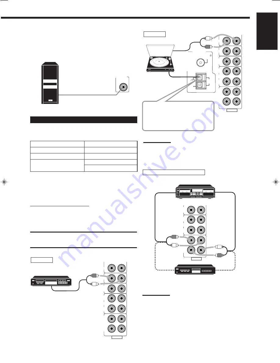
Connecting the subwoofer speaker

You can enhance the bass by connecting a subwoofer.
Connect the input jack of a powered subwoofer to the
SUBWOOFER OUT jack on the rear panel, using a cable with RCA
pin plugs (not supplied).

SUBWOOFER

OUT

Powered subwoofer

Connecting Audio/Video Components

You can connect the following audio/video components to this
receiver. Refer also to the manuals supplied with your components.

Audio Components

Video Components

• CD player*

• DVD player*

• Turntable

• TV

• Cassette deck

• DBS tuner*

or MD recorder*

• VCR

*

You can connect these components using the methods described
in “Analog connections” (below) or  in “Digital connections” (see
page 7).

Analog connections

Audio component connections

Use the cables with RCA pin plugs (not supplied).
Connect the white plug to the audio left jack, and the red plug to the
audio right jack.

CAUTION:

If you connect a sound-enhancing device such as a graphic equalizer
between the source components and this receiver, the sound output
through this receiver may be distorted.

RIGHT

LEFT

AUDIO

VCR

IN

(PLAY)

OUT

(REC)

CD

PHONO

TV SOUND

/DBS

TAPE

/MD

IN

(PLAY)

OUT

(REC)

CD player

To audio output

CD player

RIGHT

LEFT

AUDIO

VCR

IN

(PLAY)

OUT

(REC)

CD

PHONO

TV SOUND

/DBS

TAPE

/MD

IN

(PLAY)

OUT

(REC)

ANTENNA

AM

EXT

AM

LOOP

FM  75  
COAXIAL

Turntable

Turntable

To audio
output

If an earth cable is provided for
your turntable, connect the cable
to the terminal marked (

H

) of the

ANTENNA terminals on the rear
panel.

Note:

Any turntables incorporating a small-output cartridge such as an MC
(moving-coil type) must be connected to this receiver through a
commercial head amplifier or step-up transformer. Direct connection
may result in insufficient volume.

RIGHT

LEFT

AUDIO

VCR

IN

(PLAY)

OUT

(REC)

CD

PHONO

TV SOUND

/DBS

TAPE

/MD

IN

(PLAY)

OUT

(REC)

Cassette deck or MD recorder

Cassette deck

To audio output

To audio input

MD recorder

Note:

You can connect either a cassette deck or an MD recorder to the
TAPE/MD jacks. When connecting an MD recorder to the TAPE/MD
jacks, change the source name, which will be shown on the display
when selected as the source, to “M D.” See page 11 for details.

If your audio components have a COMPU LINK-3 terminal
See also page 26 for detailed information about the connection and
the COMPU LINK-3 remote control system.

To audio input

To audio output

EN01-07.RX-6500V[J]

99.12.16, 1:17 PM

5

Summary of Contents for RX-6500VBK - Dolby Digital/DTS Audio/Video Receiver

Page 1: ...APE MD VCR PHONO THEATER LIVE CLUB DANCE CLUB HALL PAVILLION DIGITAL AUTO SOURCE NAME SOURCE NAME ONE TOUCH OPERATION INPUT ATT DSP MODE MULTI CURSOR ANALOG DIGITAL SURROUND FM AM MASTER VOLUME OFF _ ON POWER D I G I T A L ON CATV CH VCR CH RM SRX6500J REMOTE CONTROL POWER TVSOUND DBS TV SURROUND SURROUND MODE CD DISC SOUND VCR VCR AUDIO CATV CONTROL CD PHONO SLEEP CATV SAT DVD TAPE MD FM AM ANALO...

Page 2: ...connected Correct Notes If REAR SPK and CENTER SPK are set to NONE you cannot select Surround mode No sounds come out of the center speaker even if it is connected When REAR SPK and CENTER SPK are set to NONE the same effect as used for the 3D PHONIC is applied to any DAP mode to maintain the surround elements with only two front speakers Page 20 On page 20 in the DSP mode cycle it is written that...

Page 3: ...OT EXPOSE THIS APPLIANCE TO RAIN OR MOISTURE CAUTION To reduce the risk of electrical shocks fire etc 1 Do not remove screws covers or cabinet 2 Do not expose this appliance to rain or moisture Caution POWER switch Disconnect the mains plug to shut the power off completely The POWER switch in any position does not disconnect the mains line The power can be remote controlled For U S A This equipmen...

Page 4: ...dio Video Components 5 Connecting the Power Cord 7 Putting Batteries in the Remote Control 7 Basic Operations 8 Turning the Power On and Off Standby 8 Selecting the Source to Play 8 Adjusting the Volume 9 Selecting the Front Speakers 9 Muting the Sound 9 Adjusting the Subwoofer Output Level 10 Attenuating the Input Signal 10 Reinforcing the Bass 10 Adjusting the Tone 10 Basic Settings 11 Recording...

Page 5: ...WER ON RX 6500V AUDIO VIDEO CONTROL RECEIVER STANDBY PHONES SPEAKERS 1 2 ADJUST SETTING MEMORY DVD CD TAPE MD VCR PHONO THEATER LIVE CLUB DANCE CLUB HALL PAVILLION DIGITAL AUTO SOURCE NAME SOURCE NAME ONE TOUCH OPERATION INPUT ATT DSP MODE MULTI CURSOR ANALOG DIGITAL SURROUND FM AM MASTER VOLUME OFF _ ON POWER D I G I T A L Ÿ fi fl TV SOUND DBS IMPORTANT To use the MULTI CURSOR buttons w on the fr...

Page 6: ... disassemble the receiver or remove screws covers or cabinet Do not expose the receiver to rain or moisture Checking the Supplied Accessories Check to be sure you have all of the following items which are supplied with the receiver The number in the parentheses indicates the quantity of the pieces supplied Remote Control 1 Batteries 2 AM Loop Antenna 1 FM Antenna 1 If anything is missing contact y...

Page 7: ...following speakers Two pairs of front speakers to produce normal stereo sound One pair of rear speakers to enjoy the surround effect One center speaker to produce more effective surround effect to emphasize human voices One subwoofer to enhance the bass IMPORTANT After connecting the speakers listed above set the speaker setting information properly to obtain the best possible DSP effect For detai...

Page 8: ...CR IN PLAY OUT REC CD PHONO TV SOUND DBS TAPE MD IN PLAY OUT REC CD player To audio output CD player RIGHT LEFT AUDIO VCR IN PLAY OUT REC CD PHONO TV SOUND DBS TAPE MD IN PLAY OUT REC ANTENNA AM EXT AM LOOP FM 75 COAXIAL Turntable Turntable To audio output If an earth cable is provided for your turntable connect the cable to the terminal marked H of the ANTENNA terminals on the rear panel Note Any...

Page 9: ...T REC DIGITAL2 CD DIGITAL1 DVD DIGITAL3 DBS PCM DOLBYDIGITAL DTS DIGITALIN VIDEO VIDEO S VIDEO MONITOR OUT VCR IN PLAY OUT REC DBS DVD RIGHT LEFT AUDIO DVD A B D F DIGITALOUT PCM DOLBYDIGITAL DTS C E VCR Å To left right channel audio output ı To left right channel audio input Ç To composite video output Î To composite video input To S video output for better playback picture quality Ï To S video i...

Page 10: ... control put two supplied batteries first When using the remote control aim the remote control directly at the remote sensor on the receiver 1 On the back of the remote control remove the battery cover 2 Insert batteries Make sure to match the polarity to and to 3 Replace the cover If the range or effectiveness of the remote control decreases replace the batteries Use two R6P SUM 3 AA 15F type dry...

Page 11: ...acks or a DBS tuner to the TV SOUND DBS jacks change the source name that appears on the display See page 11 for details When you press one of the source selecting buttons on the remote control marked above with an asterisk the receiver automatically turns on Signal and speaker indicators on the display The signal indicators light up to indicate the incoming channel signals Only the indicators for...

Page 12: ...l ONLY When you have connected two pairs of the front speakers you can select which to use Pressing SPEAKERS 1 or SPEAKERS 2 activates the respective set of speakers To use the speakers connected to the FRONT SPEAKERS 1 terminals press SPEAKERS 1 to set it in the _ ON position and press SPEAKERS 2 to set it in the OFF position To use the speakers connected to the FRONT SPEAKERS 2 terminals press S...

Page 13: ...s connected using the analog terminals This function does not take effect when digital input is selected Reinforcing the Bass With this Bass Boost function you can boost the bass level Before you start remember There is a time limit in doing the following steps If the setting is canceled before you finish start from step 1 again On the front panel ONLY 1 Press ADJUST repeatedly until BASSBOOST wit...

Page 14: ...he recording For digital to digital recording You can record the selected digital input through the receiver to a digital recording device connected to the DIGITAL OUT terminal Analog to digital and digital to analog recordings are not possible When the source is the digital recording equipment such as an MD only linear PCM signals can be recorded While recording you can listen to the selected sou...

Page 15: ...he delay time of the sound from the center speaker comparing that of the sound from the front speakers If the distance from your listening point to the center speaker is equal to that to the front speakers select 0 msec As the distance to the center speaker becomes shorter increase the delay time 1 msec increase or decrease in delay time corresponds to 30 cm decrease or increase in distance When s...

Page 16: ...ow Frequency Effect Attenuator Setting If the bass sound is distorted while playing back a source using Dolby Digital or DTS Digital Surround follow the procedure below This function takes effect only when the subwoofer LFE signals come in with SUBWOOFER set to Yes On the front panel ONLY 1 Press SETTING repeatedly until LFE ATT Low Frequency Effect Attenuator appears on the display Once you have ...

Page 17: ...l you change it 1 Follow the steps in Digital Input DIGITAL IN Terminal Setting to the left 2 Press the source selecting button CD TAPE MD TV SOUND DBS or DVD for which you want to change the input mode from analog input to digital input 3 Press ANALOG DIGITAL repeatedly until the digital input mode you want appears on the display Each time you press the button the input mode changes as follows No...

Page 18: ... Press SETTING repeatedly until SUBWOOFER appears on the display Once you have pressed SETTING MULTI CURSOR fi can be also used for selecting SUBWOOFER The display changes to show the current setting 2 Press MULTI CURSOR fi to select YES or NO YES Select this when a subwoofer is used NO Select this when no subwoofer is used Storing the Basic Settings and Adjustments One Touch Operation JVC s One T...

Page 19: ...ted channel number is flashing on the display The selected channel number stops flashing The station is assigned to the selected channel number 5 Repeat steps 1 to 4 until you store all the stations you want To erase a stored preset station Storing a new station on a used number erases the previously stored one Tuning in Stations Manually On the front panel ONLY 1 Press FM AM to select the band Th...

Page 20: ...s The AUTO MUTING indicator goes off on the display To tune in a preset station On the front panel 1 Press FM AM to select the band The MULTI CURSOR fi buttons can be now used for operating the tuner Each time you press the button the band alternates between FM and AM 2 Press MULTI CURSOR fi repeatedly until PRESET appears on the display 3 Press MULTI CURSOR to select a preset channel station Pres...

Page 21: ...REAR SPK and CENTER SPK is set to NONE see page 12 DAP modes The sound heard in a concert hall or club consists of direct sound and indirect sound early reflections and reflections from behind Direct sounds reach the listener directly without any reflection On the other hand indirect sounds are delayed by the distances of the ceiling and walls These direct sounds and indirect sounds are the most i...

Page 22: ...e page 7 DTS Digital Surround DTS Digital Surround is a discrete 5 1 channel digital audio format available on CD LD and DVD software To watch the soundtracks of video software bearing the mark the receiver can provide you with DTS Digital Surround decoder DTS Digital Surround is automatically selected according to software played back and the speaker arrangement you have done To enjoy the softwar...

Page 23: ...al Surround You cannot select the Surround mode with this speaker setting Front speaker TV Center speaker Front speaker Each time you press DSP MODE on the front panel or SURROUND MODE on the remote control the DSP modes change as follows By pressing DSP MODE THEATER LIVE CLUB DANCE CLUB HALL PAVILION HEAD PHONE 3D ACTION DSP OFF DSP mode is canceled To activate the Surround mode press SURROUND bu...

Page 24: ...o select the effect level As you press it the effect level changes as follows As the number increases the selected DAP mode becomes stronger Adjusting the 3D PHONIC Modes Once you have adjusted the 3D PHONIC modes the adjustment is memorized for each 3D PHONIC mode Before you start remember Make sure that you have set the speaker information correctly see page 12 There is a time limit in doing the...

Page 25: ...rt from step 1 again You cannot adjust the rear speaker output levels when you have set REAR SPK to NONE See page 12 You cannot adjust the center speaker output level when you have set CENTER SPK to NONE See page 12 From the remote control 1 Press SURROUND to activate an appropriate Surround mode PRO LOGIC DOLBY DIGITAL or DTS SURROUND Each time you press the button the Surround mode turns on and ...

Page 26: ...tone comes out of the center speaker when CENTER SPK is set to NONE see page 12 No test tone comes out of the rear speakers when REAR SPK is set to NONE see page 12 SURROUND MODE TEST TONE L Left front speaker TEST TONE LS Left rear speaker TEST TONE RS Right rear speaker TEST TONE C Center speaker TEST TONE R Right front speaker SOUND TEST 3 4 CNTR TEST 5 6 REAR L On the front panel You can also ...

Page 27: ...ls 4 Adjust the effect level 1 Press ADJUST repeatedly until DSP EFFECT appears on the display Once you have pressed ADJUST MULTI CURSOR fi also can be used for selecting DSP EFFECT The display changes to show the current setting 2 Press MULTI CURSOR to select the effect level As you press it the effect level changes as follows As the number increases JVC Theater Surround becomes stronger 4 Adjust...

Page 28: ...Pro Logic play back a software encoded with Dolby Surround and labeled with DOLBY SURROUND mark To enjoy Dolby Digital play back a software encoded with Dolby Digital and labeled with D I G I T A L mark To enjoy DTS Digital surround play back a software encoded with DTS Digital Surround and labeled with mark To cancel the Dolby DTS Surround mode Press SURROUND again SURROUND OFF appears on the dis...

Page 29: ...elected component begins playing immediately In both cases the previously selected source continues playing without sound for a few seconds Turntable CD player Cassette deck or MD recorder COMPU LINK 3 SYNCHRO Automatic Power On Off Standby only possible with the COMPU LINK 3 connection Both the CD player and cassette deck or MD recorder turn on and off standby along with the receiver When you tur...

Page 30: ...is RECEIVER AMP If the AV COMPU LINK terminal on the TV is AV COMPU LINK EX DVD player IMPORTANT Connect to the terminal indicated in the illustration DO NOT connect to the TV terminal VCR CASE2 If the DVD player and VCR are not equipped with the S video terminals CASE1 If the DVD player and VCR are equipped with the S video terminals CASE3 If only the VCR is equipped with the S video terminal CAS...

Page 31: ...ceiver into the AC outlets unplug their AC power cords first 2 Connect your VCR DVD player TV and this receiver using the cables with the monaural mini plugs not supplied See CONNECTIONS 1 on the previous page 3 Connect the audio input output jacks on VCR DVD player TV and this receiver using the cables with RCA pin plug See pages 5 and 6 4 Connect the video input output jacks on VCR DVD player TV...

Page 32: ... number 30 press 10 10 then 10 Operating JVC s Audio Video Components You can operate JVC s audio and video components with this receiver s remote control since control signals for JVC components are preset in the remote control IMPORTANT To operate JVC s audio components using this remote control You need to connect JVC audio components through the COMPU LINK 3 SYNCHRO jacks see page 26 in additi...

Page 33: ...EO Sets the input mode either TV or VIDEO TV VOL Adjusts the volume TV CH Changes the channels RETURN Alternates between the previously selected channel and the current channel 1 9 0 100 Selects the channels CD player changer After pressing CD DISC you can perform the following operations on a CD player changer 3 3 3 3 3 Starts playing 4 4 4 4 4 Returns to the beginning of the current or previous ...

Page 34: ...wing buttons can be used for operating the TV TV POWER Turns on and off the TV TV VOL Adjusts the volume TV VIDEO Sets the input mode either TV or VIDEO After pressing TV SOUND DBS you can perform the following operations on the TV TV CH Changes the channels 1 9 0 100 10 Selects the TV channels 100 10 button will function as the ENTER button if your TV requires pressing ENTER after selecting a cha...

Page 35: ...r s code two digits using buttons 1 9 and 0 See the list below to find the code Examples For a JVC product press 1 then 4 For a SONY product press 2 then 0 4 Release CATV SAT POWER Following button can be used for operating the CATV converter or the satellite tuner CATV SAT POWER Turns on and off the CATV converter or satellite tuner After pressing CATV CONTROL you can perform the following operat...

Page 36: ...ic Move speakers away from the turntable 1 Press POWER on the front panel to turn off the receiver 2 Stop the playback source 3 Turn on the receiver again and adjust the volume Press POWER on the front panel to turn off the receiver check the speaker wiring then press it again to turn on the receiver again If OVERLOAD does not disappear though speaker wiring is not short circuited consult your dea...

Page 37: ... 21 dBm to 15 dBm 660 nm 30 nm Corresponding to Linear PCM Dolby Digital and DTS Digital Surround with sampling frequency 32 kHz 44 1 kHz 48 kHz Audio Output Level TAPE MD VCR 220 mV Digital Output Optical DIGITAL OUTPUT Signal wave length 660 nm Output level 21 dBm to 15 dBm Signal to Noise Ratio 66 IHF 78 IHF PHONO 70 dB 78 dB at REC OUT CD TAPE MD TV SOUND DBS VCR DVD 87 dB 80 dB Frequency Resp...

Page 38: ...6 at 1 kHz Stereo Separation at REC OUT 35 dB at 1 kHz Alternate Channel Selectivity 45 dB 400 kHz Frequency Response 30 Hz to 15 kHz 0 5 dB 3 dB AM tuner Tuning Range 530 kHz to 1 710 kHz Usable Sensitivity Loop antenna 400 µV m Signal to Noise Ratio 50 dB 100 mV m General Power Requirements AC 120V 60 Hz Power Consumption 290 W 390 VA at operation 2 W in standby mode Dimensions W x H x D 435 mm ...

Page 39: ...E CENTER LOCATIONS 10 New Maple Avenue Pine Brook NJ 07058 9641 973 396 1000 5665 Corporate Avenue Cypress CA 90630 0024 714 229 8011 13 Cummings Park Woburn MA 01801 781 376 9100 705 Enterprise Street Aurora IL 60504 8149 630 851 7855 10700 Hammerly Suite 110 Houston TX 77043 713 935 9331 890 Dubuque Avenue South San Francisco CA 94080 1804 650 871 2666 1500 Lakes Parkway Lawrenceville GA 30243 5...

Page 40: ... attachment not provided with the products or if the model number or serial number has been altered tampered with defaced or removed 2 Initial installation and installation and removal for repair 3 Operational adjustments covered in the Owner s Manual normal maintenance video and audio head cleaning 4 Damage that occurs in shipment due to act of God and cosmetic damage 5 Signal reception problems ...

Page 41: ...VICTOR COMPANY OF JAPAN LIMITED EN J VC 1299HIMMDWJEIN ...

Reviews: