(No.MB159)1-7
3.3
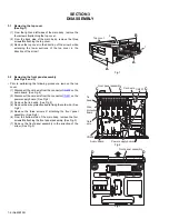
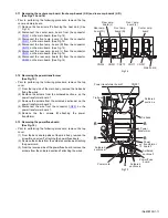
Removing the rear panel
(See Fig.4)
• Prior to performing the following procedure, remove the top
cover.
(1) From the back side of the main body, remove the strain
relief from the rear panel in the direction of the arrow.
(2) Remove the twenty-seven screws
E
and four screws
F
attaching the rear panel.
Fig.4
3.4
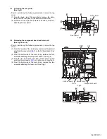
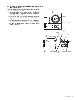
Removing the component board and tuner unit
(See Figs.5 and 6)
• Prior to performing the following procedure, remove the top
cover.
(1) From the top side of the main body, disconnect the parallel
wire from the connector
CN511
on the S-Video board. (See
Fig.5)
(2) From the back side of the main body, remove the four
screws
G
attaching the component board. (See Fig.6)
(3) From the top side of the main body, disconnect the card
wire from the connector
CN1
on the tuner unit. (See Fig.5)
(4) From the back side of the main body, remove the two
screws
H
attaching the tuner unit. (See Fig.6)
Fig.5
Fig.6
F
Rear panel
E
F
E
E
Strain relief
F
E
CN511
S-Video board
Parallel wire
Component board
Tuner
CN1
G
H
Summary of Contents for RX-6040B
Page 19: ... M E M O ...
Page 45: ... M E M O ...

