background image

7

CD

IN

OUT

(REC)

IN

(PLAY)

OUT

(REC)

VCR

TV SOUND

IN

AUDIO

RIGHT

LEFT

IN

(PLAY)

TAPE
/CDR

R

R

L

R

L

L

Connecting Audio/Video Components

Turn the power off to all components before making connections.

You can connect the following audio/video components to this receiver. Refer also to the manuals supplied with your
components.
• Audio Components:

CD player

*

 and Cassette deck (or CD recorder

*

)

• Video Components:

VCR, TV

*

, and DVD player

*

*

You can connect these components using the methods described in “Analog connections” (below) and/or in “Digital connections” (see page 10).

Analog Connections

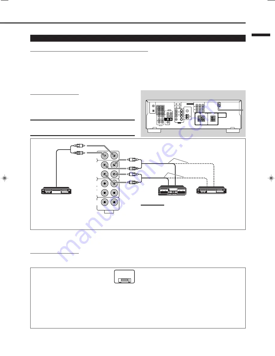
Audio component connections

Use cables with RCA pin plugs (not supplied).
Connect the white plug to the audio left jack and the red plug
to the audio right jack.

CAUTION:

If you connect a sound-enhancing device such as a graphic equalizer
between the source components and this receiver, the sound output
through this receiver may be distorted.

Rear panel

CD recorder

Cassette deck

CD player

Note:

You can connect either a cassette deck or a CD recorder to the
TAPE/CDR jacks. When connecting a CD recorder to the TAPE/
CDR jacks, change the source name to CDR so that “CDR”
appears on the display when selected as the source. See page 12
for details.

If your audio components have a COMPU LINK jack

See also page 29 for detailed information about the connections with the COMPU LINK remote control system.

Video component connections

Use cables with RCA pin plugs (not supplied).
Connect the white plug to the audio left jack, the red plug to the audio right jack, and the yellow plug to the video jack.

By using these terminals, you can get better picture quality in the
order of— Composite video < S-video < Component video.

However, 

remember that the video signals from one type of

input terminals are sent only through the video output
terminals of the same type.

Therefore, if a recording video component and a playing video
component are connected to the receiver through different types of
video terminals, you cannot record the picture from the playing
component onto the recording component. In addition, if the TV and
a playing video component are connected to the receiver through
different types of video terminals, you cannot view the playback
picture from the playing component on the TV.

TO BE CONTINUED TO THE NEXT PAGE

To get better picture quality

RX-6030VBK and RX-6032VSL have the following
video terminals and you can use any of them to
connect a video component:
• VIDEO (composite video) terminals
• S-VIDEO terminals
• COMPONENT VIDEO terminals

If your video components have S-video (Y/C-separation) terminals,
connect them using an S-video cable (not supplied).
If your video components have component video (Y, P

B

, P

R

)

terminals, connect them using a component video cable (not
supplied).

To audio input

RX-6030V

RX-6032V

ONLY

To audio output

Getting Started

To audio output

01-10_RX-60_5030[J]f

02.11.28, 13:46

7

Summary of Contents for RX-5030VBK

Page 1: ... BOOST PRO LOGIC DSP H PHONE AUTO MUTING TUNED STEREO TA NEWS INFO VOLUME INPUT ATT EON RDS SLEEP CH 1 2 ANALOG L LINEAR PCM DIGITAL C R S WFR LFE LS RS S STANDBY STANDBY ON PHONES D I G I T A L P R O L O G I C SURROUND DSP DVD MULTI SPEAKERS ON OFF SUBWOOFER OUT FM MODE MEMORY ON OFF FM AM TUNING DVD VCR CD FM AM TAPE CDR TV SOUND SURROUND DSP OFF DIMMER INPUT DIGITAL RX 6030V AUDIO VIDEO CONTROL...

Page 2: ...RNE CORRESPONDANTE DE LA PRISE ET POUSSER JUSQUAU FOND THIS DIGITAL APPARATUS DOES NOT EXCEED THE CLASS B LIMITS FOR RADIO NOISE EMISSIONS FROM DIGITAL APPARATUS AS SET OUT IN THE INTERFERENCE CAUSING EQUIPMENT STANDARD ENTITLED DIGITAL APPARATUS ICES 003 OF THE DEPARTMENT OF COMMUNICATIONS CET APPAREIL NUMERIQUE RESPECTE LES LIMITES DE BRUITS RADIOELECTRIQUES APPLICABLES AUX APPAREILS NUMERIQUES ...

Page 3: ...justing Subwoofer Output Level 21 Tuner Operations 22 Tuning in to Stations Manually 22 Using Preset Tuning 22 To Store the Preset Stations 22 To Tune in to a Preset Station 23 Selecting the FM Reception Mode 23 Creating Realistic Sound Fields 24 Using Surround Modes 26 Using DSP Modes 27 Using DVD MULTI Playback Mode RX 6030VBK RX 6032VSL only 28 Activating DVD MULTI Playback Mode 28 COMPU LINK R...

Page 4: ...RY button 22 23 i SETTING button 15 o SET button 15 19 MULTI JOG dial 15 19 a EXIT button 15 19 s ADJUST button 19 d For RX 6030VBK and RX 6032VSL Source selection buttons 11 DVD MULTI DVD VCR TV SOUND CD TAPE CDR FM AM SOURCE NAME button 12 f For RX 5030VBK and RX 5032VSL Source selection buttons 11 DVD VCR TV SOUND CD TAPE CDR FM AM SOURCE NAME button 12 STANDBY STANDBY ON PHONES D I G I T A L P...

Page 5: ...E CDR CD DVD DVD MULTI FM AM TV SOUND VCR 6 FM MODE button 23 7 SURROUND button 26 8 DIMMER button 13 9 TV VIDEO button 34 35 0 VCR CH buttons 34 36 TV CATV CH buttons 34 35 STANDBY ON buttons 11 34 36 AUDIO TV CATV VCR DVD SLEEP button 14 Operating buttons for audio video components 3 8 7 4 FF REW 33 34 36 CD DISC button 33 ANALOG DIGITAL button 17 SURROUND DSP OFF button 26 27 DSP button 27 MUTI...

Page 6: ...9 7 1 2 4 3 5 6 p Rear Panel RX 6030VBK RX 6032VSL Rear Panel RX 6030VBK RX 6032VSL See pages in parentheses for details 1 DIGITAL IN terminals 10 Coaxial DIGITAL 1 DVD Optical DIGITAL 2 CD 2 Audio input output terminals 6 9 Audio components CD IN TAPE CDR Video components VCR TV SOUND IN DVD IN SUBWOOFER OUT 3 COMPU LINK 4 terminals 29 4 AV COMPU LINK III terminals 30 5 FM AM ANTENNA terminals 5 ...

Page 7: ...terference When a power failure occurs or when you unplug the power cord the preset settings such as preset FM or AM channels and sound adjustments may be erased within a few days Checking the Supplied Accessories Check to be sure you have all of the following supplied accessories The number in parentheses indicates the quantity of each piece supplied Remote control 1 Batteries 2 AM loop antenna 1...

Page 8: ...AKER IMPEDANCE 8 16 To left front speaker To right surround speaker To center speaker To right front speaker To left surround speaker SUBWOOFER OUT Powered subwoofer To subwoofer input 7 How to connect the subwoofer Connect the input jack of a powered subwoofer to the SUBWOOFER OUT jack on the rear panel using a cable with RCA pin plugs not supplied Refer also to the manual supplied with your subw...

Page 9: ...connections with the COMPU LINK remote control system Video component connections Use cables with RCA pin plugs not supplied Connect the white plug to the audio left jack the red plug to the audio right jack and the yellow plug to the video jack By using these terminals you can get better picture quality in the order of Composite video S video Component video However remember that the video signal...

Page 10: ...CR TV SOUND IN ANTENNA AUDIO RIGHT LEFT IN PLAY TAPE CDR SUBWOOFER OUT DVD IN RIGHT LEFT FRONT SUB WOOFER CENTER AUDIO COAXIAL FM 75 RIGHT SURR REAR LEFT MONITOR OUT DVD IN OUT REC VCR IN PLAY VIDEO S VIDEO DVD IN MONITOR OUT VCR IN Y PB PR R R L L A B C D E G RX 6030V RX 6032V ONLY F AM LOOP AM EXT CD IN OUT REC IN PLAY OUT REC VCR TV SOUND IN ANTENNA AUDIO RIGHT LEFT IN PLAY TAPE CDR SUBWOOFER O...

Page 11: ...IN MONITOR OUT DVD IN OUT REC VCR IN PLAY DVD B A R L RX 5030VBK RX 5032VSL AM LOOP AM EXT ANTENNA COAXIAL FM 75 SUBWOOFER OUT DVD IN RIGHT LEFT FRONT SUB WOOFER CENTER AUDIO RIGHT SURR REAR LEFT VIDEO S VIDEO Y PB PR DVD IN MONITOR OUT VCR IN MONITOR OUT DVD IN OUT REC VCR IN PLAY DVD F G E D A B C Rear panel To use software encoded with Dolby Digital or DTS Digital Surround connect the DVD playe...

Page 12: ...efore using the remote control put in two the supplied batteries first When using the remote control aim the remote control directly at the remote sensor on the front panel 1 On the back of the remote control remove the battery cover 2 Insert batteries Make sure to match the polarity to and to 3 Replace the cover If the range or effectiveness of the remote control decreases replace the batteries U...

Page 13: ... control again The STANDBY lamp lights up Note A small amount of power is consumed in standby mode To turn the power off completely unplug the AC power cord Selecting the Source to Play Press one of the source selection buttons The selected source name appears on the display RX 6030VBK RX 6032VSL On the front panel From the remote control DVD MULTI Select the DVD player for viewing a digital video...

Page 14: ...one of the following inconveniences A different source name will appear on the display when you select the target component You cannot use the digital input see page 16 for the CD recorder You cannot use the COMPU LINK remote control system see page 29 to operate the target component SOURCE NAME TAPE CDR PHONES jack SPEAKERS ON OFF MUTING VOLUME MASTER VOLUME control Remote NOT Front panel Remote ...

Page 15: ...irectly to the headphones For multi channel sources the front left right center and surround left right channel signals are down mixed and then sent to the headphones You can enjoy multi channel sound sources using the headphones Note While in the HEADPHONE mode you cannot use any Surround DSP modes see page 24 Basic Operations After using the headphones 1 Press SPEAKERS ON OFF on the front panel ...

Page 16: ...e recording you can listen to the selected sound source at whatever sound level you like without affecting the sound levels of the recording Note The output volume level tone adjustment see page 20 and Surround DSP modes see pages 26 and 27 do not affect the recording Turning Off the Power with the Sleep Timer You can fall asleep while listening to music Sleep Timer Press SLEEP on the remote contr...

Page 17: ...e front speaker setting If you have selected SMALL for the front speaker setting you cannot select LARGE for the center and surround speaker settings Basic Settings Using MULTI JOG Dial After connecting and placing speakers you need to make basic settings for the following items according to your listening conditions Speaker information see the next column and page 16 Digital input terminal source...

Page 18: ... O O O O O O O O O O O 7 Dynamic range compression D_COMPRESSION You can compress the dynamic range difference between maximum sound and minimum sound of the reproduced sound This is useful when using surround sound at night This function takes effect only when playing back a source using Dolby Digital MID Select this when you want to reduce the dynamic range a little initial setting MAX Select th...

Page 19: ...e pages 7 9 and the digital connection see page 10 methods you need to select the input mode correctly 1 Press one of the source selection buttons DVD TV SOUND CD or TAPE CDR for which you want to change the input mode Note Among the sources listed above you can select the digital input only for the sources for which you have selected the digital input terminals See Selecting the Digital Input Ter...

Page 20: ...S ON OFF FM MODE MEMORY FM AM TUNING DVD VCR CD FM AM TAPE CDR TV SOUND SURROUND DSP OFF DIMMER INPUT DIGITAL RX 6030V AUDIO VIDEO CONTROL RECEIVER INPUT ANALOG INPUT ATT FM AM RESET SOURCE NAME Attenuating the Input Signal When the input level of the analog source is too high the sound will be distorted If this happens you need to attenuate the input signal level to prevent the distortion Once th...

Page 21: ...utput level SUBWFR LEVEL Speakers output level FRONT L R LEVEL CENTER LEVEL SURR L R LEVEL Effect level for DAP modes EFFECT Panorama control for Pro Logic II Music PANORAMA CTRL You can also use the remote control to adjust these items see pages 20 and 21 7 Operating buttons Buttons To do ADJUST Enter the receiver into the sound adjusting mode MULTI JOG Select an item to adjust after pressing ADJ...

Page 22: ...fer output level SUBWFR LEVEL Adjust the subwoofer output level 10 to 10 in 1 step interval 0 is the initial setting Note Subwoofer output level cannot be adjusted in the following cases When SUBWOOFER NO is selected for the subwoofer setting see page 15 When the HEADPHONE mode is in use see page 13 7 Speakers output level Adjust the speakers output level so that you can hear sounds from each spea...

Page 23: ... display and a test tone comes out of the speakers in the following order Check whether you can hear the tone through all the speakers at an equal level or not Note If the center and surround speakers are set to NONE no test tone is available 3 Select a speaker you want to adjust Press one of the following buttons FRONT L Left front speaker FRONT R Right front speaker CENTER Center speaker SURR L ...

Page 24: ... 30 FM and 15 AM stations To Store the Preset Stations Before you start remember There is a time limit in doing the following steps If the setting is canceled before you finish start again from step 2 1 Tune in to the station you want to preset see Tuning in to Stations Manually If you want to store the FM reception mode for this station select the FM reception mode you want See Selecting the FM R...

Page 25: ...work for the tuner operation Each time you press the button the band alternates between FM and AM 2 Press 10 keys 1 10 10 to select a preset channel number For channel number 5 press 5 For channel number 15 press 10 then 5 For channel number 20 press 10 then 10 For channel number 30 press 10 10 then 10 Note When you use 10 keys be sure that they are activated for the tuner not for the CD or other ...

Page 26: ...o Logic and the double D symbol are trademarks of Dolby Laboratories You can use the following Surround and DSP modes to reproduce a realistic sound field Surround modes 7 Dolby Dolby Pro Logic II Dolby Digital 7 DTS Digital Surround DSP modes 7 DAP modes 7 All Channel Stereo Surround modes 7 Dolby Dolby Pro Logic II Dolby Pro Logic II has a multi channel playback format to decode all 2 channel so...

Page 27: ...are either analog or digital except Dolby Digital and DTS Digital Surround and can give you a real being there feeling When one of the DAP modes is selected the DSP indicator lights up on the display Modes SURROUND DOLBY DTS PL II PL II LIVE DANCE HALL PAVILION ALL CH Signals OFF stereo DIGITAL SURROUND MOVIE MUSIC CLUB CLUB STEREO Dolby Digital 䡬 䡬 Multi channel Dolby Digital 䡬 䡬 䡬 2 channel DTS ...

Page 28: ... S U R R O U N D SURROUND DSP DVD MULTI SPEAKERS ON OFF SUBWOOFER OUT FM MODE MEMORY ON OFF FM AM TUNING DVD VCR CD FM AM TAPE CDR TV SOUND SURROUND DSP OFF DIMMER INPUT DIGITAL RX 6030V AUDIO VIDEO CONTROL RECEIVER INPUT ANALOG INPUT ATT FM AM RESET SOURCE NAME Front panel Remote control SURROUND REMOTE CONTROL RM SRX6030J DISPLAY MODE 2 Press SURROUND The appropriate Surround mode will be activa...

Page 29: ...r adjustment operation see pages 19 to 21 Selected Surround DSP mode SURROUND OFF stereo DOLBY DIGITAL DTS SURROUND PL II MOVIE PL II MUSIC LIVE CLUB DANCE CLUB HALL PAVILION ALL CH STEREO All Channel Stereo Adjustable items FRONT L LEVEL FRONT R LEVEL SUBWFR LEVEL FRONT L LEVEL FRONT R LEVEL CENTER LEVEL SURR L LEVEL SURR R LEVEL SUBWFR LEVEL FRONT L LEVEL FRONT R LEVEL CENTER LEVEL SURR L LEVEL ...

Page 30: ...te input jacks on the rear of the receiver see page 9 and set the DVD player to the analog discrete output mode On the front panel DVD MULTI 1 Press DVD MULTI Note When you select DVD MULTI as the source to play Surround DSP mode is canceled and SURROUND and DSP buttons do not work 2 Select the analog discrete output mode on the DVD player and start playing a DVD Refer also to the manual supplied ...

Page 31: ...n remote control the receiver automatically turns on and changes the source to the component On the other hand if you select a new source on the receiver or on the remote control the selected component begins playing immediately In both cases the previously selected source continues playing without sound for a few seconds Automatic Power On Off Standby only possible with the COMPU LINK 3 and COMPU...

Page 32: ...R correctly see Selecting the Video Input Terminal VIDEO IN DVD VIDEO IN VCR on page 16 RX 5030VBK RX 5032VSL 7 AV COMPU LINK connection Note You can connect to the TV with the AV COMPU LINK EX or AV COMPU LINK III terminal A TV with AV COMPU LINK RECEIVER AMP terminal can not be used 7 Video cable connection Connect the DVD player and or the VCR to this receiver using the VIDEO composite video te...

Page 33: ...VCR or on the remote control to get the same result AV COMPU LINK Remote Control System One Touch DVD Play Simply by starting playback on the DVD player you can view the DVD playback without setting other switches manually When the DVD player is connected through the analog input jacks on this receiver and analog input is selected the receiver automatically turns on and changes the source to DVD o...

Page 34: ...st the center speaker output level SURR L LEVEL Adjust the left surround speaker output level SURR R LEVEL Adjust the right surround speaker output level TEST Turn on or off the test tone output Note When you use the 10 keys to operate your target source after sound adjustments press the corresponding source selection button first so that the 10 keys work for your target source Tuner You can alway...

Page 35: ...ck Press 1 0 5 then 1 2 then 3 Cassette deck After pressing TAPE CDR you can use the following buttons for the cassette deck operations 3 Start playback FF Fast wind a tape from left to right REW Fast wind a tape from right to left 7 Stop playback or recording 8 Pause playback To release press 3 REC PAUSE Press this button to enter recording pause Press this button then 3 to start recording Note B...

Page 36: ...VCRs can accept two types of control signals remote code A and B Before using this remote control make sure that the remote control code of the VCR connected to the VCR jacks is set to code A When using the remote control aim the remote control directly at the remote sensor on each component not on the receiver RX 6030VBK RX 6032VSL RX 5030VBK RX 5032VSL TV You can always use the following buttons...

Page 37: ...is entered Manufacturers codes for TV Manufacturer Codes JVC 01 Hitachi 10 Magnavox 02 Mitsubishi 03 Panasonic 04 11 RCA 05 Samsung 12 Sanyo 13 Sharp 06 Sony 07 Toshiba 08 Zenith 09 01 is the initial setting Operating JVC s Audio Video Components Operating Other Manufacturers Video Equipment To change the transmission signals for operating a CATV converter 1 Set TV CATV selector to CATV 2 Press an...

Page 38: ...l cannot operate the equipment Operating Other Manufacturers Video Equipment TEST MENU ENTER LEVEL RETURN SURR R SURR L SUBWFR CENTER FRONT R FRONT L 100 1 4 7 P 10 2 5 8 0 3 6 9 10 TA NEWS INFO To change the transmission signals for operating a VCR 1 Press and hold STANDBY ON VCR 2 Press VCR 3 Enter manufacturer s codes using buttons 1 9 and 0 4 Release STANDBY ON VCR Now you can perform the foll...

Page 39: ...Y ON on the front panel to turn off the receiver After unplugging the power cord consult your dealer Remove the obstruction Replace batteries in the remote control Press SOUND or source selection buttons first then press the button you want to use See pages 32 36 POSSIBLE CAUSE The power cord is not plugged in Speaker signal cables are not connected An incorrect source is selected Muting is activa...

Page 40: ...Control Bass 100 Hz 10 dB Treble 10 kHz 10 dB Video Video Input Sensitivity Impedance Composite video DVD VCR 1 V p p 75 Ω S video DVD VCR Y luminance 1 V p p 75 Ω C chrominance burst 0 286 V p p 75 Ω Component video DVD VCR Y luminance 1 V p p 75 Ω PB PR 0 7 V p p 75 Ω Video Output Level Impedance Composite video VCR MONITOR OUT 1 V p p 75 Ω S video VCR MONITOR OUT Y luminance 1 V p p 75 Ω C chro...

Page 41: ... VCR TV SOUND DVD 87 dB 78 dB Frequency Response 8 Ω CD TAPE CDR VCR TV SOUND DVD 20 Hz to 20 kHz 1 dB Tone Control Bass 100 Hz 10 dB Treble 10 kHz 10 dB Video Video Input Sensitivity Impedance Composite video DVD VCR 1 V p p 75 Ω Video Output Level Impedance Composite video VCR MONITOR OUT 1 V p p 75 Ω Synchronization Negative Signal to Noise Ratio 45 dB FM tuner IHF Tuning Range 87 5 MHz to 108 ...

Page 42: ...cleaning 4 Damage that occurs in shipment due to act of God and cosmetic damage 5 Signal reception problems and failures due to line power surge 6 Video Pick up Tubes CCD Image Sensor Cartridge Stylus Needle are covered for 90 days from the date of purchase 7 Batteries except that Rechargeable Batteries are covered for 90 days from the date of purchase There are no express warranties except as lis...

Page 43: ...rvicer or visit our website at www JVC com Remember to retain your Bill of Sale for Warranty Service Do not service the television yourself Caution To prevent electrical shock do not open the cabinet There are no user serviceable parts inside Please refer to qualified service personnel for repairs Accessories To purchase accessories for your JVC product please call toll free 1 800 882 2345 or on t...

Page 44: ...EN 0103NHMMDWJEIN J VC VICTOR COMPANY OF JAPAN LIMITED 2002 VICTOR COMPANY OF JAPAN LIMITED ...

Page 45: ...LINEAR PCM DIGITAL C R S WFR LFE LS RS S STANDBY STANDBY ON PHONES D I G I T A L P R O L O G I C SURROUND DSP DVD MULTI SPEAKERS ON OFF SUBWOOFER OUT FM MODE MEMORY ON OFF FM AM TUNING DVD VCR CD FM AM TAPE CDR TV SOUND SURROUND DSP OFF DIMMER INPUT DIGITAL RX 6030V AUDIO VIDEO CONTROL RECEIVER SETTING MULTI JOG SET ADJUST EXIT INPUT ANALOG MASTER VOLUME INPUT ATT FM AM RESET SOURCE NAME TA NEWS I...

Page 46: ...UES DE CLASSE B PRESCRITES DANS LA NORME SUR LE MATERIEL BROUILLEUR APPAREILS NUMERIQUES NMB 003 EDICTEE PAR LE MINISTRE DES COMMUNICATIONS For U S A This equipment has been tested and found to comply with the limits for a Class B digital device pursuant to part 15 of the FCC Rules These limits are designed to provide reasonable protection against harmful interference in a residential installation...

Page 47: ...et Station 23 Selecting the FM Reception Mode 23 Creating Realistic Sound Fields 24 Using Surround Modes 26 Using DSP Modes 27 Using DVD MULTI Playback Mode RX 6030VBK RX 6032VSL only 28 Activating DVD MULTI Playback Mode 28 COMPU LINK Remote Control System 29 AV COMPU LINK Remote Control System 30 Operating JVC s Audio Video Components 32 Operating Audio Components 32 Operating Video Components 3...

Page 48: ...MEMORY button 22 23 i SETTING button 15 o SET button 15 19 MULTI JOG dial 15 19 a EXIT button 15 19 s ADJUST button 19 d For RX 6030VBK and RX 6032VSL Source selection buttons 11 DVD MULTI DVD VCR TV SOUND CD TAPE CDR FM AM SOURCE NAME button 12 f For RX 5030VBK and RX 5032VSL Source selection buttons 11 DVD VCR TV SOUND CD TAPE CDR FM AM SOURCE NAME button 12 STANDBY STANDBY ON PHONES D I G I T A...

Page 49: ... CD DVD DVD MULTI FM AM TV SOUND VCR 6 FM MODE button 23 7 SURROUND button 26 8 DIMMER button 13 9 TV VIDEO button 35 36 0 VCR CH buttons 35 37 TV CATV CH buttons 35 36 STANDBY ON buttons 11 35 37 AUDIO TV CATV VCR DVD SLEEP button 14 Operating buttons for audio video components 3 8 7 4 FF REW 33 35 37 CD DISC button 33 ANALOG DIGITAL button 17 SURROUND DSP OFF button 26 27 DSP button 27 MUTING bu...

Page 50: ...Y 8 9 7 1 2 4 3 5 6 p Rear Panel RX 6030VBK RX 6032VSL Rear Panel RX 6030VBK RX 6032VSL See pages in parentheses for details 1 DIGITAL IN terminals 10 Coaxial DIGITAL 1 DVD Optical DIGITAL 2 CD 2 Audio input output terminals 6 9 Audio components CD IN TAPE CDR Video components VCR TV SOUND IN DVD IN SUBWOOFER OUT 3 COMPU LINK 4 terminals 29 4 AV COMPU LINK III terminals 30 5 FM AM ANTENNA terminal...

Page 51: ...ll shielded against interference When a power failure occurs or when you unplug the power cord the preset settings such as preset FM or AM channels and sound adjustments may be erased within a few days Checking the Supplied Accessories Check to be sure you have all of the following supplied accessories The number in parentheses indicates the quantity of each piece supplied Remote control 1 Batteri...

Page 52: ... SPEAKER IMPEDANCE 8 16 To left front speaker To right surround speaker To center speaker To right front speaker To left surround speaker SUBWOOFER OUT Powered subwoofer To subwoofer input 7 How to connect the subwoofer Connect the input jack of a powered subwoofer to the SUBWOOFER OUT jack on the rear panel using a cable with RCA pin plugs not supplied Refer also to the manual supplied with your ...

Page 53: ...n about the connections with the COMPU LINK remote control system Video component connections Use cables with RCA pin plugs not supplied Connect the white plug to the audio left jack the red plug to the audio right jack and the yellow plug to the video jack By using these terminals you can get better picture quality in the order of Composite video S video Component video However remember that the ...

Page 54: ...EC VCR TV SOUND IN ANTENNA AUDIO RIGHT LEFT IN PLAY TAPE CDR SUBWOOFER OUT DVD IN RIGHT LEFT FRONT SUB WOOFER CENTER AUDIO COAXIAL FM 75 RIGHT SURR REAR LEFT MONITOR OUT DVD IN OUT REC VCR IN PLAY VIDEO S VIDEO DVD IN MONITOR OUT VCR IN Y PB PR R R L L A B C D E G RX 6030V RX 6032V ONLY F AM LOOP AM EXT CD IN OUT REC IN PLAY OUT REC VCR TV SOUND IN ANTENNA AUDIO RIGHT LEFT IN PLAY TAPE CDR SUBWOOF...

Page 55: ...ONITOR OUT DVD IN OUT REC VCR IN PLAY DVD B A R L RX 5030VBK RX 5032VSL AM LOOP AM EXT ANTENNA COAXIAL FM 75 SUBWOOFER OUT DVD IN RIGHT LEFT FRONT SUB WOOFER CENTER AUDIO RIGHT SURR REAR LEFT VIDEO S VIDEO Y PB PR DVD IN MONITOR OUT VCR IN MONITOR OUT DVD IN OUT REC VCR IN PLAY DVD F G E D A B C Rear panel To use software encoded with Dolby Digital or DTS Digital Surround connect the DVD player us...

Page 56: ...ol Before using the remote control put in two the supplied batteries first When using the remote control aim the remote control directly at the remote sensor on the front panel 1 On the back of the remote control remove the battery cover 2 Insert batteries Make sure to match the polarity to and to 3 Replace the cover If the range or effectiveness of the remote control decreases replace the batteri...

Page 57: ...N AUDIO on the remote control again The STANDBY lamp lights up Note A small amount of power is consumed in standby mode To turn the power off completely unplug the AC power cord Selecting the Source to Play Press one of the source selection buttons The selected source name appears on the display RX 6030VBK RX 6032VSL On the front panel From the remote control DVD MULTI Select the DVD player for vi...

Page 58: ...ents however you may experience one of the following inconveniences A different source name will appear on the display when you select the target component You cannot use the digital input see page 16 for the CD recorder You cannot use the COMPU LINK remote control system see page 29 to operate the target component SOURCE NAME TAPE CDR PHONES jack SPEAKERS ON OFF MUTING VOLUME MASTER VOLUME contro...

Page 59: ...ls are sent directly to the headphones For multi channel sources the front left right center and surround left right channel signals are down mixed and then sent to the headphones You can enjoy multi channel sound sources using the headphones Note While in the HEADPHONE mode you cannot use any Surround DSP modes see page 24 After using the headphones 1 Press SPEAKERS ON OFF on the front panel to a...

Page 60: ... While recording you can listen to the selected sound source at whatever sound level you like without affecting the sound levels of the recording Note The output volume level tone adjustment see page 20 and Surround DSP modes see pages 26 and 27 do not affect the recording Turning Off the Power with the Sleep Timer You can fall asleep while listening to music Sleep Timer Press SLEEP on the remote ...

Page 61: ... select LARGE for the front speaker setting If you have selected SMALL for the front speaker setting you cannot select LARGE for the center and surround speaker settings Basic Settings Using MULTI JOG Dial After connecting and placing speakers you need to make basic settings for the following items according to your listening conditions Speaker information see the next column and page 16 Digital i...

Page 62: ...TV O O O O O O O O O O O O 7 Dynamic range compression D_COMPRESSION You can compress the dynamic range difference between maximum sound and minimum sound of the reproduced sound This is useful when using surround sound at night This function takes effect only when playing back a source using Dolby Digital MID Select this when you want to reduce the dynamic range a little initial setting MAX Selec...

Page 63: ... pages 7 9 and the digital connection see page 10 methods you need to select the input mode correctly 1 Press one of the source selection buttons DVD TV SOUND CD or TAPE CDR for which you want to change the input mode Note Among the sources listed above you can select the digital input only for the sources for which you have selected the digital input terminals See Selecting the Digital Input Term...

Page 64: ...TI SPEAKERS ON OFF FM MODE MEMORY FM AM TUNING DVD VCR CD FM AM TAPE CDR TV SOUND SURROUND DSP OFF DIMMER INPUT DIGITAL RX 6030V AUDIO VIDEO CONTROL RECEIVER INPUT ANALOG INPUT ATT FM AM RESET SOURCE NAME Attenuating the Input Signal When the input level of the analog source is too high the sound will be distorted If this happens you need to attenuate the input signal level to prevent the distorti...

Page 65: ...output level SUBWFR LEVEL Speakers output level FRONT L R LEVEL CENTER LEVEL SURR L R LEVEL Effect level for DAP modes EFFECT Panorama control for Pro Logic II Music PANORAMA CTRL You can also use the remote control to adjust these items see pages 20 and 21 7 Operating buttons Buttons To do ADJUST Enter the receiver into the sound adjusting mode MULTI JOG Select an item to adjust after pressing AD...

Page 66: ...bwoofer output level SUBWFR LEVEL Adjust the subwoofer output level 10 to 10 in 1 step interval 0 is the initial setting Note Subwoofer output level cannot be adjusted in the following cases When SUBWOOFER NO is selected for the subwoofer setting see page 15 When the HEADPHONE mode is in use see page 13 7 Speakers output level Adjust the speakers output level so that you can hear sounds from each ...

Page 67: ...ing on the display and a test tone comes out of the speakers in the following order Check whether you can hear the tone through all the speakers at an equal level or not Note If the center and surround speakers are set to NONE no test tone is available 3 Select a speaker you want to adjust Press one of the following buttons FRONT L Left front speaker FRONT R Right front speaker CENTER Center speak...

Page 68: ...p to 30 FM and 15 AM stations To Store the Preset Stations Before you start remember There is a time limit in doing the following steps If the setting is canceled before you finish start again from step 2 1 Tune in to the station you want to preset see Tuning in to Stations Manually If you want to store the FM reception mode for this station select the FM reception mode you want See Selecting the ...

Page 69: ... 10 keys now work for the tuner operation Each time you press the button the band alternates between FM and AM 2 Press 10 keys 1 10 10 to select a preset channel number For channel number 5 press 5 For channel number 15 press 10 then 5 For channel number 20 press 10 then 10 For channel number 30 press 10 10 then 10 Note When you use 10 keys be sure that they are activated for the tuner not for the...

Page 70: ...y Pro Logic and the double D symbol are trademarks of Dolby Laboratories You can use the following Surround and DSP modes to reproduce a realistic sound field Surround modes 7 Dolby Dolby Pro Logic II Dolby Digital 7 DTS Digital Surround DSP modes 7 DAP modes 7 All Channel Stereo Surround modes 7 Dolby Dolby Pro Logic II Dolby Pro Logic II has a multi channel playback format to decode all 2 channe...

Page 71: ...channel stereo software either analog or digital except Dolby Digital and DTS Digital Surround and can give you a real being there feeling When one of the DAP modes is selected the DSP indicator lights up on the display Modes SURROUND DOLBY DTS PL II PL II LIVE DANCE HALL PAVILION ALL CH Signals OFF stereo DIGITAL SURROUND MOVIE MUSIC CLUB CLUB STEREO Dolby Digital 䡬 䡬 Multi channel Dolby Digital ...

Page 72: ... A L S U R R O U N D SURROUND DSP DVD MULTI SPEAKERS ON OFF SUBWOOFER OUT FM MODE MEMORY ON OFF FM AM TUNING DVD VCR CD FM AM TAPE CDR TV SOUND SURROUND DSP OFF DIMMER INPUT DIGITAL RX 6030V AUDIO VIDEO CONTROL RECEIVER INPUT ANALOG INPUT ATT FM AM RESET SOURCE NAME Front panel Remote control SURROUND REMOTE CONTROL RM SRX6030J DISPLAY MODE 2 Press SURROUND The appropriate Surround mode will be ac...

Page 73: ...ration see pages 19 to 21 Selected Surround DSP mode SURROUND OFF stereo DOLBY DIGITAL DTS SURROUND PL II MOVIE PL II MUSIC LIVE CLUB DANCE CLUB HALL PAVILION ALL CH STEREO All Channel Stereo Adjustable items FRONT L LEVEL FRONT R LEVEL SUBWFR LEVEL FRONT L LEVEL FRONT R LEVEL CENTER LEVEL SURR L LEVEL SURR R LEVEL SUBWFR LEVEL FRONT L LEVEL FRONT R LEVEL CENTER LEVEL SURR L LEVEL SURR R LEVEL SUB...

Page 74: ...screte input jacks on the rear of the receiver see page 9 and set the DVD player to the analog discrete output mode On the front panel DVD MULTI 1 Press DVD MULTI Note When you select DVD MULTI as the source to play Surround DSP mode is canceled and SURROUND and DSP buttons do not work 2 Select the analog discrete output mode on the DVD player and start playing a DVD Refer also to the manual suppl...

Page 75: ... a connected component or on its own remote control the receiver automatically turns on and changes the source to the component On the other hand if you select a new source on the receiver or on the remote control the selected component begins playing immediately In both cases the previously selected source continues playing without sound for a few seconds Automatic Power On Off Standby only possi...

Page 76: ...e VCR correctly see Selecting the Video Input Terminal VIDEO IN DVD VIDEO IN VCR on page 16 RX 5030VBK RX 5032VSL 7 AV COMPU LINK connection Note You can connect to the TV with the AV COMPU LINK EX or AV COMPU LINK III terminal A TV with AV COMPU LINK RECEIVER AMP terminal can not be used 7 Video cable connection Connect the DVD player and or the VCR to this receiver using the VIDEO composite vide...

Page 77: ... play 3 button on the VCR or on the remote control to get the same result One Touch DVD Play Simply by starting playback on the DVD player you can view the DVD playback without setting other switches manually When the DVD player is connected through the analog input jacks on this receiver and analog input is selected the receiver automatically turns on and changes the source to DVD or DVD MULTI RX...

Page 78: ...CATV TA NEWS INFO DISPLAY MODE A V CONTROL RECEIVER TAPE CDR CD DVD FM AM TV SOUND VCR ANALOG DIGITAL AUDIO TV CATV VCR DVD TEST MENU ENTER LEVEL RETURN SURROUND DSP CD DISC SLEEP REC PAUSE FM MODE SURROUND DSP DIMMER TV VIDEO BASSBOOST MUTING OFF VCR CH TV CATV CH VOLUME SURR R SURR L SUBWFR CENTER FRONT R FRONT L 100 1 4 7 P 10 2 5 8 0 3 6 9 10 REMOTE CONTROL RM SRX6030J REW FF TVVOLUME STANDBY ...

Page 79: ...number 2 Select a track number always enter two digits 3 Start playback Examples Selecting disc number 3 track number 2 and starting playback Press 3 then 0 2 then 3 Selecting disc number 10 track number 5 and starting playback Press 1 0 then 0 5 then 3 Selecting disc number 105 track number 12 and starting playback Press 1 0 5 then 1 2 then 3 CD recorder After pressing TAPE CDR you can use the fo...

Page 80: ...FO DISPLAY MODE A V CONTROL RECEIVER TAPE CDR CD DVD DVD MULTI FM AM TV SOUND VCR ANALOG DIGITAL RX 6030VBK RX 6032VSL RX 5030VBK RX 5032VSL Tuner You can always use the following buttons FM AM Alternate between FM and AM After pressing FM AM you can use the following buttons for the tuner operations 1 10 10 Select a preset channel number directly For channel number 5 press 5 For channel number 15...

Page 81: ...ENU ENTER LEVEL RETURN SURROUND DSP CD DISC SLEEP REC PAUSE FM MODE SURROUND DSP DIMMER TV VIDEO BASSBOOST MUTING OFF VCR CH TV CATV CH VOLUME SURR R SURR L SUBWFR CENTER FRONT R FRONT L 100 1 4 7 P 10 2 5 8 0 3 6 9 10 REMOTE CONTROL RM SRX6030J REW FF TVVOLUME STANDBY ON TV CATV TA NEWS INFO DISPLAY MODE A V CONTROL RECEIVER TAPE CDR CD DVD DVD MULTI FM AM TV SOUND VCR ANALOG DIGITAL VCR You can ...

Page 82: ...brand of TV try each one until the correct one is entered Manufacturers codes for TV Manufacturer Codes JVC 01 Hitachi 10 Magnavox 02 Mitsubishi 03 Panasonic 04 11 RCA 05 Samsung 12 Sanyo 13 Sharp 06 Sony 07 Toshiba 08 Zenith 09 01 is the initial setting To change the transmission signals for operating a CATV converter 1 Set TV CATV selector to CATV 2 Press and hold STANDBY ON TV CATV 3 Press TV S...

Page 83: ... changed this remote control cannot operate the equipment To change the transmission signals for operating a VCR 1 Press and hold STANDBY ON VCR 2 Press VCR 3 Enter manufacturer s codes using buttons 1 9 and 0 4 Release STANDBY ON VCR Now you can perform the following operations on the VCR STANDBY ON VCR Turn on or off the VCR VCR CH Change the channels After pressing VCR you can perform the follo...

Page 84: ...turn off the receiver After unplugging the power cord consult your dealer Remove the obstruction Replace batteries in the remote control Press SOUND or source selection buttons first then press the button you want to use See pages 32 37 POSSIBLE CAUSE The power cord is not plugged in Speaker signal cables are not connected An incorrect source is selected Muting is activated An incorrect input mode...

Page 85: ...ne Control Bass 100 Hz 10 dB Treble 10 kHz 10 dB Video Video Input Sensitivity Impedance Composite video DVD VCR 1 V p p 75 Ω S video DVD VCR Y luminance 1 V p p 75 Ω C chrominance burst 0 286 V p p 75 Ω Component video DVD VCR Y luminance 1 V p p 75 Ω PB PR 0 7 V p p 75 Ω Video Output Level Impedance Composite video VCR MONITOR OUT 1 V p p 75 Ω S video VCR MONITOR OUT Y luminance 1 V p p 75 Ω C c...

Page 86: ...D DVD 87 dB 78 dB Frequency Response 8 Ω CD TAPE CDR VCR TV SOUND DVD 20 Hz to 20 kHz 1 dB Tone Control Bass 100 Hz 10 dB Treble 10 kHz 10 dB Video Video Input Sensitivity Impedance Composite video DVD VCR 1 V p p 75 Ω Video Output Level Impedance Composite video VCR MONITOR OUT 1 V p p 75 Ω Synchronization Negative Signal to Noise Ratio 45 dB FM tuner IHF Tuning Range 87 5 MHz to 108 0 MHz Usable...

Page 87: ...EN FR 0103NHMMDWJEIN J VC VICTOR COMPANY OF JAPAN LIMITED 2003 VICTOR COMPANY OF JAPAN LIMITED ...

Reviews: