background image

A14

Controlling the Multiple Product

RS-232C

RJ-45

Header (5 bytes)

Payload (4 bytes)

Checksum 

(1byte)

command

Prefix code 

#0 

Prefix code 

#1

Set 

ID

Payload 

Type

# of 

payload 

bytes

Command 

data #0

data #1

data #2

CS #0

Ack Set Wide 

Mode

0xCC

0x55

0

4

0xC2

0xE0 : OK


0xE1 : NG

reserved (0xFF) reserved 

(0xFF)

Header XOR 

Payload

Read Wide 

Mode

0xCC

0x33

1

4

0xC2

reserved (0x00) reserved (0x00) reserved 

(0x00)

Header XOR 

Payload

Ack Read 

Wide Mode

0xCC

0x55

1

4

0xC2

0xE0 : OK


0xE1 : NG

0 : Normal/Full


1 : Wide


2 : Zoom


3 : Stretch/

Panoramic

reserved 

(0x00)

Header XOR 

Payload

Set Video 

System

0xCC

0x33

0

4

0xCC

0 : 60Hz


1 : 50Hz

reserved (0xFF) reserved 

(0xFF)

Header XOR 

Payload

Ack Set Video 

System

0xCC

0x55

0

4

0xCC

0xE0 : OK


0xE1 : NG

reserved (0xFF) reserved 

(0xFF)

Header XOR 

Payload

Read Video 

System

0xCC

0x33

1

4

0xCC

reserved (0x00) reserved (0x00) reserved 

(0x00)

Header XOR 

Payload

Ack Read 

Video System

0xCC

0x55

1

4

0xCC

0xE0 : OK


0xE1 : NG

0 : 60Hz


1 : 50Hz

reserved 

(0xFF)

Header XOR 

Payload

RS232C CheckSum

Header (5 bytes)

Payload (4 bytes)

Checksum 

(1byte)

command Prefix code 

#0 

Prefix code 

#1

Set 

ID

Payload 

Type

# of payload 

bytes

Command 

data #0

data #1

data #2

CS #0

Set Power

0xCC

0x33

0

4

0x10

"0 : 0ff


1 : On"

reserved 

(0x00)

reserved 

(0x00)

Header XOR 

Payload

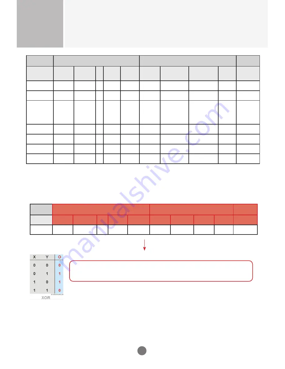
We can make CheckSum with Header (5 bytes) and Payload(4 bytes).

(Prefix code#0) XOR (Prefix code#1) XOR (Set ID) XOR (Command Payload Type) XOR 

(# of Payload bytes) XOR (Command) XOR (data #0) XOR (data #1) XOR (data#2)  = 

CheckSum

For example:
(0xCC) XOR (0x33) XOR (0x01 = Set ID) XOR (0x00) XOR (0x04) XOR (0x10) XOR (0x01 = 

ON) XOR (0x00) XOR (0x00) = 0xEB

Summary of Contents for RS-840UD

Page 1: ...4K Ultra HD LCD Display MODELS RS 840UD OWNER S MANUAL K W K W K W WNER S MANUAL K W ...

Page 2: ...pletely or wipe dust off before plugging in the cord You may be electrocuted due to excess moisture n If you do not intend to use the display for a long time unplug the power cord from the display Covering dust can cause a fire or insulation deterioration can cause electric leakage electric shock or fire n Insert the power plug firmly so it cannot come loose A loose connection can cause fire Hold ...

Page 3: ...ce If you continue to use without taking proper measures electrical shock or fire can occur n If you dropped the display or the case is broken turn off the display and unplug the power cord If you continue to use without taking proper measures electrical shock or fire can occur Contact Customer Service n Do not drop an object on or apply impact to the display Do not throw any toys or objects at th...

Page 4: ...cloth or spray water or other liquids directly onto the display An electric shock may occur Do not use chemicals such as benzene paint thinners or alcohol n Keep the display away from water Fire or electric shock accident can occur n Avoid high temperatures and humidity n Do not put or store flammable substances near the display There is a danger of explosion or fire n Keep the display clean at al...

Page 5: ...r abnormal condition a Ambient condition Well ventilated place is recommended to set up the system b Power and screen saver Periodical power off or screen saver is needed after long term display n Operating usages to protect against image sticking due to long term static display a Suitable operating time Under 18 hours a day b Static information display recommended to use with moving image Cycling...

Page 6: ...luded with your display If an accessory is missing please contact the dealer where you purchased the display v The accessories included may differ from the images shown below Remote Control Batteries AAA 2 Power Cord Power Cord for EU Optional Quick Start Guide Stand Stand Screws 6 pieces CD ROM User s Manual ...

Page 7: ...image shown in the user s guide could be different from the actual image No Item Description 1 Power indicator Indicate power on or sleep mode status Power on LED lights up Power off LED off 2 IR Receiver Receive incoming remote control commands 1 2 ...

Page 8: ... a PC VGA port 6 PC Audio Input Port Connect to a PC s line audio port 7 Component Video Input Ports Connect to an external device such as a VCR STB or a DVD player 8 Stereo Audio Line Out Connect an external audio system or headphones INPUT MENU VOL VOL RS 232 IN RS 232 OUT ETHERNET PC MUSIC COMPONENT VIDEO AUDIO OUT RGB PC PC AUDIO IN AUDIO OUT DPTICAL Y V R AUDIO COMPONENT GOOD L Pr Cr Pb Cb HD...

Page 9: ...v HDMI Supports High Definition input and HDCP High bandwidth Digital Content Protection Some devices require HDCP in order to display HD signals 11 USB Ports Connect to a USB device such as a USB flash drive or USB hard disk drive 12 HDMI UHD60 Ports Connect an HDMI equipment such as a computer camcorder or multimedia player which are able to output 4x HDMI with individually 1080p 60Hz resolution...

Page 10: ...nstall the batteries matching the correct polarity Install two 1 5V AA batteries 3 Close the battery cover Dispose the used batteries in the recycle bin to prevent environmental pollution OK Enter th e submenu Confirm the selection Input Switch the input source Menu Display OSD on screen display menu Multimedia Enter the multimedia mode Wide Change the display mode Exit Exit OSD menu Mute Mute the...

Page 11: ...een side down on a flat and cushioned surface Then attach the stand as shown in the illustration 2 Secure the stand with the six included screws Please fasten with a screwdriver Note If you do not fasten the screws the display may fall which may result in damage to the product ...

Page 12: ...11 Removing the Stand 1 Place the display with the screen side down on a flat and cushioned surface Then remove the screws 2 Detach the stand from the display Stand Installation ...

Page 13: ...e These mounts are purchased separately Refer to the instructions included with the wall mount for more information v The handles are designed for carrying VESA compatible wall bracket WxH Screw type Mount holes number 400 x 600 mm M8 4 Mounting on a Wall INPU T MEN U VOL VOL Handle Handle ...

Page 14: ...DCP High bandwidth Digital Content Protection Some devices require HDCP in order to display HD signals AUDIO IN HDMI 1 2 3 HDMI to DVI signal cable VCR DVD Set top Box Note Dolby Digital is not supported Recommended Connection Resolution Picture Mode HDMI Connection 3840 x 2160 30Hz dynamic AUDIO IN HDMI 1 2 3 HDMI signal cable VCR DVD Set top Box Display Display ...

Page 15: ...nal Devices PC Connection Check that the computer display and the peripherals are turned off Then connect the signal input cable A Connecting with an HDMI Signal Input Cable HDMI Display Audio cable HDMI UHD60 Connection 3840 x 2160 60Hz Four HDMI ports form a UHD 60Hz Each connection transmits 1080P 60Hz HDMI signal cable UHD60 4 3 2 1 4 3 2 1 Display HDMI signal cable HDMI signal cable HDMI sign...

Page 16: ...s Speaker DPTICAL Display Optical audio cable Audio amplifier Component Connection Y V R AUDIO COMPOSITE GOOD L Pr Cr Pb Cb Display Component AV cable VCR DVD Set top Box Composite Video Connection Y V R AUDIO COMPOSITE GOOD L Pr Cr Pb Cb Display Composite AV cable VCR DVD Set top Box ...

Page 17: ... External Devices Power Connection INPU T MEN U VOL VOL Rear side of the display Power outlet USB Connection Ethernet Connection USB 1 2 Display USB Flash Drive ETHERNET Network Display Ethernet RJ 45 cable Power cord ...

Page 18: ...Volume Up Increase the volume level Adjust the settings increase the value 4 Volume Down Decrease the volume level Adjust the settings decrease the value 5 Power Turn the display on off 6 Input Switch the input source 7 Menu Display hide the OSD on screen display menu or return to the previous menu INPUT MENU VOL VOL INPUT MENU VOL VOL 1 2 3 4 5 6 7 ...

Page 19: ...Adjust the audio settings Setup Adjust the general settings such as CEI setting OSD language and etc Ethernet Configure the network settings Wide Select how the picture displays on the screen Sleep Timer Set the timer to turn the display off at the preset time Note OSD On Screen Display The OSD function enables you to adjust the screen status conveniently since it provides graphical presentation ...

Page 20: ...ect the menu item 5 Press the OK or u button to enter the submenu 6 Use the t u button to adjust the setting select the option 7 Use the OK button to confirm the setting 8 Press the MENU button to return to the previous menu exit the OSD menu operation using the remote control Display OSD menu Select a main menu Enter the selected menu Select a menu item Enter the submenu Adjust the setting Confir...

Page 21: ...urce Note You can also access the Input menu by pressing the INPUT button on the remote control The available menu options varies depending on the input source If the menu items are appears in gray this indicates that those functions are not available ...

Page 22: ...t a preset view option optimized for different viewing conditions Custom User can use the user defined settings as they wish Cinema This mode is normally used in movie Soft image can be seen in this mode The picture is somewhat darker than other mode OSD Menus ...

Page 23: ...level for enjoying video games Note Picture Mode option is not available if the input source is PC Gamma Select the appropriate setting of dark scenery With greater gamma value dark scenery looks brighter Backlight Adjust the backlight that affects the overall brilliance of the picture Contrast Adjust the difference between the light and dark levels in the picture Brightness Adjust the brightness ...

Page 24: ...ition vertically Horizontal Size Set the horizontal size of the screen Vertical Size Set the vertical size of the screen Fine Tune Adjust the focus of the display This item allows you to remove any horizontal noise and clear or sharpen the image of characters Picture Menu continue Note Size Position menu is not available if the input source is HDMI UHD60 The available menu options varies depending...

Page 25: ...lect from the predetermined color temperatures Red Gain Green Gain Blue Gain Adjust the red green blue gain settings to your preference Red Offset Green Offset Blue Offset Adjust the red green blue offset settings to your preference Reset Color Temperature Reset all Color Temperature settings to the factory default settings ...

Page 26: ...uce the noise level Digital NR Reduce the noise level of digital signals Film Mode Produce smoother motion picture when viewing movies from video players connected via HDMI Note Advanced Picture option is not available if the input source is PC Only Local Dimming and MEMC options are available if the input source is HDMI UHD60 Reset Picture Settings Reset all Picture settings to the factory defaul...

Page 27: ... the smooth and steady volume level function Bass Adjust the bass level to your preference Treble Adjust the treble level to your preference Balance Adjust the sound balance between the left and right speakers Lip Sync Adjust to match the movements and the lips of the person talking on the screen Speakers Turn the built in speakers on or off OSD Menus ...

Page 28: ...em Analog Audio Out Select the analog audio mode Equalizer Settings Customize the equalizer settings To adjust the settings do the following i Press the t u button to select the option and select OK to enter the submenu ii Press the p q button to adjust the setting Reset Audio Settings Reset all Audio settings to the factory default settings Select OK to reset all settings Audio Menu continue ...

Page 29: ...on Device Search Search for CEI devices Note Device Search option is only available if CEI function is enabled Menu Language Select the on screen menu language Power Indicator Enable or disable the power indicator on the front of the display when the display is turned on Wired Control Specify the type of network connection ...

Page 30: ...name assignment to each display when several displays are connected via RS 232C for display Enter the ID number and select Set to confirm the setting System Information Display the system information of the display Select System Information to view the system information OSD Menus ...

Page 31: ...30 Menu Option Description Reset All Settings Return the display parameters on all menus to the factory default settings Select OK to reset all settings Setup Menu continue OSD Menus ...

Page 32: ...e the user defined settings as they wish IP Address Subnet Mask Def Gateway Pref DNS Alt DNS Enter the respective network parameters Connect Verify the network connection Note Check with your Information Technology Provider for the correct setting Be sure the RJ 45 cable is properly connected OSD Menus ...

Page 33: ...justing to the different size Note The available menu options varies depending on the input source Wide menu is not available if the input source is 4k2k The option is either Panoramic or Stretch depend on input screen format Panoramic Standard screen format ex 4 3 Stretch Wide screen format ex 16 9 OSD Menus ...

Page 34: ...33 Sleep Timer Set the timer to turn the display off at the preset time OSD Menus Note You can also access the Sleep Timer menu by pressing the SLEEP button on the remote control ...

Page 35: ... asf Video VC 1 WMV9 Advanced Profile wmv VC 1 WMV9 Simple and Main Profiles wma H 264 MPEG 4 AVC AVI DivX avi Video Audio H 264 AVC divx MPEG 1 Layer 1 2 3 AC 3 MPEG 2 TS Transport Stream standard 188 byte TS and time stamped 192 byte TS ts Video H 264 AVC trp MPEG 2 tp VC 1 m2ts Audio MPEG 1 Layer I II m2t MPEG 1 Layer III MP3 mts AC 3 AAC MPEG 2 PS Program Stream VOB SVCD vob Video MPEG 1 MPEG ...

Page 36: ...to 3840 x 2160 for display Video decoding supports up to FHD 30P Basic Operation 1 Turn on the display 2 Plug a USB device to the USB port on the display 3 Press the MULTIMEDIA button on the remote control 4 Select the USB port that you want to access and press the OK button 5 Select the media type of the file you wish to play and press the OK button 6 Use the p q t u button to browse the files fo...

Page 37: ...ns from the selected song n Press the icon to pause the selected song playback Press the button to resume the playback n You can highlight the icon and press the OK button to skip to the next song n You can highlight the icon and press the OK button to skip to the previous song n Select Sort to specify the sorting method n Select View to change the type of file listing n Select Browser Photos to p...

Page 38: ...ideo 3 Press the OK button to begin the video playback n Press the icon to pause the selected video playback Press the button to resume the playback n Press the button to fast forward the video playback n Press the button to rewind the video playback n Press the button to stop the playback n Select Sort to specify the sorting method n Select View to change the type of file listing ...

Page 39: ...ide show begins from the selected photo n Press the button to pause the slide show or press the button to stop the slide show n Select Sort to specify the file sorting method n Select View to change the type of file listing n Select Setting to customize the slide show settings Shuffle Enable Disable the shuffle function Speed Set the interval time between each slide display Effect Select the trans...

Page 40: ...een 3 Use the p q button to select the aspect ratio of the display and press the OK button to confirm Normal Stretch Wide Panoramic Zoom Note The available menu options varies depending on the input source The option is either Panoramic or Stretch depend on input screen format Panoramic Standard screen format ex 4 3 Stretch Wide screen format ex 16 9 ...

Page 41: ... cable Press INPUT on the remote control to check the input signal The screen image looks abnormal l Is the screen positioned D SUB analog signal Select Auto Adjustment in Size Position menu to automatically select the optimal screen status that fits the current mode l Do thin lines appear in the background D SUB analog signal Select Auto Adjustment in Size Position menu to automatically select th...

Page 42: ... menu in Windows l Screen color is unstable or mono colored Check the connection status of the signal cable or re insert the PC video card l Do black spots appear on the screen Several pixels red green white or black color may appear on the screen which can be attributable to the unique characteristics of the LCD Panel This is not a malfunction of the LCD If any of above instructions does not work...

Page 43: ...t x Depth 1919 2mm x 1166 6mm x 394mm with stand 1919 2mm x 1105 2mm x 67mm without stand Net Weight 81 5kg with stand 77 5kg without stand Video Signal Maximum Resolution RGB 1920 x 1080 60 Hz Single HDMI 3840 x 2160 23 98 24 25 29 97 30Hz 4x HDMI 3840 x 2160 50 60Hz Component 1920 x 1080 I 50Hz Composite 480i NTSC Supported Color Format 4K2K 30Hz 4K2K 25Hz 4K2K 24Hz Up to RGB 4 4 4 8 bit 1080P o...

Page 44: ...x 1024 60Hz 11 1280 x 1024 75Hz 12 1920 x 1080 60Hz HDMI Preset Mode Single HDMI Mode No Resolution Refresh rate 1 640 x 480 P 60Hz 4 3 2 720 x 480 P 59 94Hz 3 720 x 480 P 60Hz 16 9 4 720 x 576 P 50Hz 5 1280 x 720 P 50Hz 6 1280 x 720 P 60Hz 16 9 7 1920 x 1080 I 50Hz 8 1920 x 1080 I 60Hz 16 9 9 1920 x 1080 P 50Hz 10 1920 x 1080 P 59 94Hz 11 1920 x 1080 P 60Hz 16 9 12 1920 x 1080 P 23 98Hz 13 1920 x...

Page 45: ...Hz UHD60 4x HDMI Mode No Resolution Refresh rate 1 3840 x 2160 50Hz 2 3840 x 2160 60Hz Component Mode Preset Mode Mode No Resolution Refresh rate 1 720 x 480 I 59 94Hz 2 720 x 480 P 59 94Hz 3 1280 x 720 P 60Hz 4 1920 x 1080 I 60Hz 5 720 x 576 I 50Hz 6 720 x 576 P 50Hz 7 1280 x 720 P 50Hz 8 1920 x 1080 I 50Hz Composite Mode Preset Mode Mode No Resolution 1 480i NTSC ...

Page 46: ...a Flow Control None a Communication Code Hex Code a Use a DB 9 Pin Cable RS 232C Configurations OUT IN OUT IN OUT IN OUT IN RS 232C cable not included PC Display 1 Display 2 Display 3 Display 4 PCDB9PinMale Pin No Designation Description Input Output 1 DCD Data carrier detect Input 2 RxD Receive data Input 3 TxD Transmit data Output 4 DTR Data terminal ready Output 5 GND Ground 6 DSR Data set read...

Page 47: ...the HDMI cable as shown in the illustration HDMI HDMI Display HDMI CEI statement Term Description One Touch Play Turning on the HDMI source device cause the connected Display to be turned on and switch to HDMI Input automatically Routing Control Switch Remote control or Front key Display Input to HDMI will cause the HDMI source device to be turned on System Standby Turning off the Display will cau...

Page 48: ...0 4 0x11 0xE0 OK 0xE1 NG reserved 0xFF reserved 0xFF Header XOR Payload Read Input Source 0xCC 0x33 1 4 0x11 reserved 0x00 reserved 0x00 reserved 0x00 Header XOR Payload Ack Read Input Source 0xCC 0x55 1 4 0x11 0xE0 OK 0xE1 NG 0x30 VGA1 0x40 DVI1 0x50 HDMI1 0x51 HDMI2 0x52 HDMI3 0x60 Composite1 0x70 YPbPr1 0x80 Music Port 0x90 TV1 0xA0 HDMI UHD60 reserved 0xFF Header XOR Payload Set Screen Mute 0x...

Page 49: ... 0x80 0x89 0 9 reserved 0x00 reserved 0x00 Header XOR Payload Ack Set Remote Controller Key 0xCC 0x55 0 4 0x14 0xE0 OK 0xE1 NG reserved 0xFF reserved 0xFF Header XOR Payload Set SleepTime 0xCC 0x33 0 4 0x19 0 off 1 30 min 2 60 min 3 90 min 4 120 min 5 180 min reserved 0x00 reserved 0x00 Header XOR Payload Ack Set SleepTime 0xCC 0x55 0 4 0x19 0xE0 OK 0xE1 NG reserved 0x00 reserved 0x00 Header XOR P...

Page 50: ... Mode 0xCC 0x55 0 4 0x30 0xE0 OK 0xE1 NG reserved 0xFF reserved 0xFF Header XOR Payload Read Picture Mode 0xCC 0x33 1 4 0x30 reserved 0x00 reserved 0x00 reserved 0x00 Header XOR Payload Ack Read Picture Mode 0xCC 0x55 1 4 0x30 0xE0 OK 0xE1 NG 0 Dynamic 1 Normal 2 Mild 3 User 4 Custom 5 Standard 6 Movie 7 Game 8 Vivid 9 Sport reserved 0xFF Header XOR Payload Set Brightness 0xCC 0x33 0 4 0x31 0 100 ...

Page 51: ...0xE0 OK 0xE1 NG 0 100 reserved 0xFF Header XOR Payload Set Color Temp Mode 0xCC 0x33 0 4 0x35 0 Cool 9300K 1 Medium 6500K 2 Warm 5500K 3 User Custom 4 Natural 5 3200K reserved 0x00 reserved 0x00 Header XOR Payload Ack Set Color Temp Mode 0xCC 0x55 0 4 0x35 0xE0 OK 0xE1 NG reserved 0xFF reserved 0xFF Header XOR Payload Read Color Temp Mode 0xCC 0x33 1 4 0x35 reserved 0x00 reserved 0x00 reserved 0x0...

Page 52: ... VGA Adjust Auto Mode 0xCC 0x33 0 4 0x3A reserved 0x00 reserved 0x00 reserved 0x00 Header XOR Payload Ack Set VGA Adjust Auto Mode 0xCC 0x55 0 4 0x3A 0xE0 OK 0xE1 NG reserved 0xFF reserved 0xFF Header XOR Payload Set VGA Adjust H Position 0xCC 0x33 0 4 0x3B 0 100 reserved 0x00 reserved 0x00 Header XOR Payload Ack Set VGA adjust H Position 0xCC 0x55 0 4 0x3B 0xE0 OK 0xE1 NG reserved 0xFF reserved 0...

Page 53: ...ad Color 0xCC 0x55 1 4 0x40 0xE0 OK 0xE1 NG 0 100 reserved 0xFF Header XOR Payload Set Tint 0xCC 0x33 0 4 0x41 0 50 50 0 100 50 reserved 0x00 reserved 0x00 Header XOR Payload Ack Set Tint 0xCC 0x55 0 4 0x41 0xE0 OK 0xE1 NG reserved 0xFF reserved 0xFF Header XOR Payload Read Tint 0xCC 0x33 1 4 0x41 reserved 0x00 reserved 0x00 reserved 0x00 Header XOR Payload Ack Read Tint 0xCC 0x55 1 4 0x41 0xE0 OK...

Page 54: ...ize 0xCC 0x33 1 4 0x45 reserved 0x00 reserved 0x00 reserved 0x00 Header XOR Payload Ack Read non VGA Vert Size 0xCC 0x55 1 4 0x45 0xE0 OK 0xE1 NG 0 100 reserved 0xFF Header XOR Payload Set Color Temp Red Offset 0xCC 0x33 0 4 0x46 0 255 reserved 0x00 reserved 0x00 Header XOR Payload Ack Set Color Temp Red Offset 0xCC 0x55 0 4 0x46 0xE0 OK 0xE1 NG reserved 0xFF reserved 0xFF Header XOR Payload Read ...

Page 55: ...ader XOR Payload Set Local Dimming 0xCC 0x33 0 4 0x4C 0 Off 1 On reserved 0x00 reserved 0x00 Header XOR Payload Ack Set Local Dimming 0xCC 0x55 0 4 0x4C 0xE0 OK 0xE1 NG reserved 0xFF reserved 0xFF Header XOR Payload Read Local Dimming 0xCC 0x33 1 4 0x4C reserved 0x00 reserved 0x00 reserved 0x00 Header XOR Payload Ack Read Local Dimming 0xCC 0x55 1 4 0x4C 0xE0 OK 0xE1 NG 0 Off 1 On reserved 0xFF He...

Page 56: ...x56 reserved 0x00 reserved 0x00 reserved 0x00 Header XOR Payload Ack Read Balance 0xCC 0x55 1 4 0x56 0xE0 OK 0xE1 NG 0 L50 49 L1 50 0 51 R1 100 R50 reserved 0xFF Header XOR Payload Set Volume 0xCC 0x33 0 4 0x58 0 100 reserved 0x00 reserved 0x00 Header XOR Payload Ack Set Volume 0xCC 0x55 0 4 0x58 0xE0 OK 0xE1 NG reserved 0xFF reserved 0xFF Header XOR Payload Read Volume 0xCC 0x33 1 4 0x58 reserved...

Page 57: ...ass 0xCC 0x55 1 4 0x62 0xE0 OK 0xE1 NG 0 12 12 0 24 12 reserved 0xFF Header XOR Payload Set Treble 0xCC 0x33 0 4 0x63 0 12 12 0 24 12 reserved 0x00 reserved 0x00 Header XOR Payload Ack Set Treble 0xCC 0x55 0 4 0x63 0xE0 OK 0xE1 NG reserved 0xFF reserved 0xFF Header XOR Payload Read Treble 0xCC 0x33 1 4 0x63 reserved 0x00 reserved 0x00 reserved 0x00 Header XOR Payload Ack Read Treble 0xCC 0x55 1 4 ...

Page 58: ... Out 0xCC 0x33 1 4 0x67 reserved 0x00 reserved 0x00 reserved 0x00 Header XOR Payload Ack Read Digital Audio Out 0xCC 0x55 1 4 0x67 0xE0 OK 0xE1 NG 0 Off 1 Dolby 2 PCM reserved 0xFF Header XOR Payload Set Analog Audio Out 0xCC 0x33 0 4 0x68 0 Fixed 1 Variable reserved 0x00 reserved 0x00 Header XOR Payload Ack Set Analog Audio Out 0xCC 0x55 0 4 0x68 0xE0 OK 0xE1 NG reserved 0xFF reserved 0xFF Header...

Page 59: ...xFF reserved 0xFF Header XOR Payload Set Power Indicator 0xCC 0x33 0 4 0x76 0 Off 1 On reserved 0x00 reserved 0x00 Header XOR Payload Ack Set Power Indicator 0xCC 0x55 0 4 0x76 0xE0 OK 0xE1 NG reserved 0xFF reserved 0xFF Header XOR Payload Read Power Indicator 0xCC 0x33 1 4 0x76 reserved 0x00 reserved 0x00 reserved 0x00 Header XOR Payload Ack Read Power Indicator 0xCC 0x55 1 4 0x76 0xE0 OK 0xE1 NG...

Page 60: ...er byte1 LA of device1 byte2 N OSD name of device1 0 for end byteN 1 LA of device2 byteN 2 M OSD name of device2 0 for end Header XOR Payload Set Reset All Settings 0xCC 0x33 0 4 0xAB reserved 0x00 reserved 0x00 reserved 0x00 Header XOR Payload Ack Set Reset All Settings 0xCC 0x55 0 4 0xAB 0xE0 OK 0xE1 NG reserved 0xFF reserved 0xFF Header XOR Payload Set DHCP 0xCC 0x33 0 4 0xAC reserved 0x00 rese...

Page 61: ...em 0xCC 0x55 0 4 0xCC 0xE0 OK 0xE1 NG reserved 0xFF reserved 0xFF Header XOR Payload Read Video System 0xCC 0x33 1 4 0xCC reserved 0x00 reserved 0x00 reserved 0x00 Header XOR Payload Ack Read Video System 0xCC 0x55 1 4 0xCC 0xE0 OK 0xE1 NG 0 60Hz 1 50Hz reserved 0xFF Header XOR Payload RS232C CheckSum Header 5 bytes Payload 4 bytes Checksum 1byte command Prefix code 0 Prefix code 1 Set ID Payload ...

Page 62: ...ace for future reference The model and serial number of the SET is located on the back and one side of the SET Record it below should you ever need service MODEL SERIAL Temporary noise is normal when powering ON or OFF this device For detail information about ISF please refer web site http www imagingscience com ...

Reviews: