RC-EZ31
5
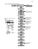
Flow of functional operation until TOC read
Check Point
Check that the voltage at the pin
63 of IC902 is OV (a moment)?
Check that the voltage at the
pin1 of IC902 + side is + 5V?
Confirm that the Focus error
Tracking error waveform at TOC reading
s-cuve signal at the pin16 of
IC902 is approx.2V p-p
Confirm that the signal from
pin14 IC902 is 0V as a
accelerated pulse during
approx.400ms
Confirm the waveform of
the Tracking error signal
at the pin14 of IC902
(See fig-1)
Confirm the eys-pattern
at the lead of TP1
Power Key
Slider turns REST
SW ON.
Automatic tuning
of TE offset
Laser ON
Detection of disc
Automatic tuning of
Focus offset
Automatic measurement of
focus A-curve amplitude
Disc is rotated
Focus servo ON
(Tracking servo ON)
Automatic measurement of
Tracking error amplitude
Automatic tuning of
Tracking error balance
Automatic tuning of
Focus error balance
Automatic tuning of
Focus error gain
Automatic tuning of
Tracking error gain
TOC reading
Play a disc
pin 14 of
IC902(TE)
VREF
Tracking
servo
off status
Tracking
servo
on
statues
Disc to be
braked to
stop
Disc status
to rotate
TOC reading
finishes
500mV/div
2mS/div Fig.1
Automatic measurement
of TE amplitude and
automatic tuning of
TE balance
Approx
1.8V
Approx 3sec
Summary of Contents for RC-EZ31A
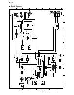
Page 8: ...XL SV320SL SV305GD XL SV308BU 8 RC EZ31 Block Diagram ...
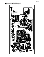
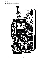
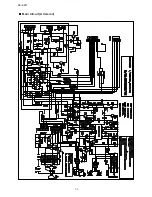
Page 9: ...RC EZ31 9 Wiring Connections US UX version ...
Page 10: ...XL SV320SL SV305GD XL SV308BU 10 RC EZ31 Wiring Connections A version ...
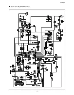
Page 11: ...RC EZ31 11 Schematic Diagrams Main Circuit US UX Version ...
Page 12: ...XL SV320SL SV305GD XL SV308BU 12 RC EZ31 Main Circuit A Version ...
Page 13: ...RC EZ31 13 Tuner Circuit US UX Version ...
Page 14: ...XL SV320SL SV305GD XL SV308BU 14 RC EZ31 Tuner Circuit A Version ...
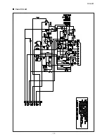
Page 15: ...RC EZ31 15 Cass Circuit ...
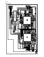
Page 16: ...XL SV320SL SV305GD XL SV308BU 16 RC EZ31 CD Circuit ...
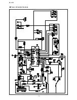
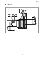
Page 17: ...RC EZ31 17 Control Circuit ...

