RC-EZ31
3
Preventing static electricity
Electrostatic discharge (ESD), which occurs when static electricity stored in the body, fabric, etc. is discharged,
can destroy the laser diode in the traverse unit (optical pcikup). Take care to prevent this when performing repairs.
1.1. Grounding to prevent damage by static electricity
Static electricity in the work area can destroy the optical pickup (laser diode) in devicessuch as DVD players.
Be careful to use proper grounding in the area where repairs are being performed.
1.1.1. Gound the workbench
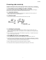
1. Ground the workbench by laying conductive material (such as a conductive sheet) or an iron plate over
it before placing the traverse unit (optical pickup) on it.
1.1.2. Ground yourself
1.
Use an anti-static wrist starp to release and static electricity built up in your body.
1.1.3. Handling the optical pcikup
1. In order to maintain quality during transport and before installation, both sides of the laser diode on the
replacement optical pickup are storted. After replacement, return the shorted parts to their original condition.
(Refer to the text.)
2. Do not use a tester to check the condition of the laserdiode in the optical pickup. The tester's internal power
source can easily destory the laser diode.
1.2. Handling the traverse unit (optical pickup)
1.
Do not subject the traverse unit (optical pcikup) to strong shocks, as it is a sensitive, complex unit.
2.
Cut off the shorted part of the flexible cable using nippers, etc. after replacing the optical pickup. For specific
details, refer to the replacement procdeure in the text. Remove the anti-static pin when replacing the traverse
unit. Be careful not to take too long a time when attaching itto the connector.
3.
Handle the flexible cable carefully as it may break when subjected to strong force.
4.
It is not possible to adjust the semi-fixed resistor that adjusts the laser power. Do not return it.
Summary of Contents for RC-EZ31A
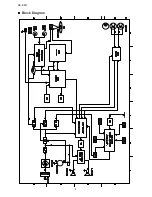
Page 8: ...XL SV320SL SV305GD XL SV308BU 8 RC EZ31 Block Diagram ...
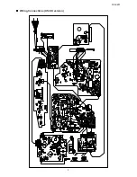
Page 9: ...RC EZ31 9 Wiring Connections US UX version ...
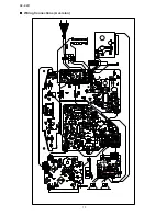
Page 10: ...XL SV320SL SV305GD XL SV308BU 10 RC EZ31 Wiring Connections A version ...
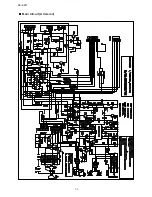
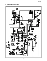
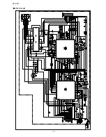
Page 11: ...RC EZ31 11 Schematic Diagrams Main Circuit US UX Version ...
Page 12: ...XL SV320SL SV305GD XL SV308BU 12 RC EZ31 Main Circuit A Version ...
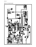
Page 13: ...RC EZ31 13 Tuner Circuit US UX Version ...
Page 14: ...XL SV320SL SV305GD XL SV308BU 14 RC EZ31 Tuner Circuit A Version ...
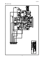
Page 15: ...RC EZ31 15 Cass Circuit ...
Page 16: ...XL SV320SL SV305GD XL SV308BU 16 RC EZ31 CD Circuit ...
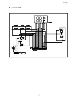
Page 17: ...RC EZ31 17 Control Circuit ...

