1-10 (No.YA228)
SECTION 3
DISASSEMBLY
3.1
DISASSEMBLY PROCEDURE
CAUTION AT DISASSEMBLY:
•
Be sure to perform the SYSTEM SETTING on the page 1-6, at the end of the procedure.
• Make sure that the power cord is disconnected from the outlet.
• Pay special attention not to break or damage the parts.
• When removing each board, remove the connectors as required. Taking notes of the connecting points (connector numbers)
makes service procedure manageable.
• Make sure that there is no bent or stain on the connectors before inserting, and firmly insert the connectors.
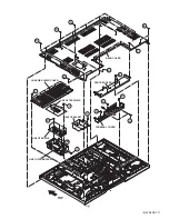
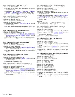
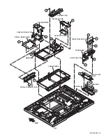
3.1.1 REMOVING THE REAR COVER (Fig.1)
(1) Remove the power cord.
(2) Remove the 17 screws
[A]
, the 4 screws
[B]
, the 8 screws
[C]
and the 3 screws
[D]
, then remove the REAR COVER.
CAUTION:
• Prior to starting the work, be sure to read the following
written instructions on the CAUTION LABEL attached to the
REAR COVER.
3.1.2 REMOVING THE TERMINAL COVER AND CENTER
COVER (Fig.1)
• Remove the REAR COVER.
(1) Remove the 6 screws
[E]
, then remove the CENTER
COVER.
(2) Remove the 7 screws
[F]
, then remove the CHASSIS
SHIELD COVER.
(3) Remove the 7 screws
[G]
, the 12 screws
[H]
, then remove
the TERMINAL COVER.
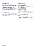
3.1.3 REMOVING THE LINE FILTER PWB (Fig.1)
• Remove the REAR COVER.
(1) Remove the 3 screw
[I]
, then remove the LINE FILTER
SHIELD.
(2) Remove the 2 screw
[J]
, then remove the INLET
BRACKET.
(3) Disconnect the connector [
CN8001
] from the MAIN
POWER UNIT.
(4) Remove the 5 screw
[K]
, the 2 screw
[L]
and the 1 screw
[M]
, then remove the LINE FILTER PWB.
Summary of Contents for PD-Z42DX4
Page 73: ...2 4 No YA228 ...
Page 115: ...PDP COLOUR TELEVISION INSTRUCTIONS PD Z42DX4 ENGLISH LCT1774 001A ...
Page 167: ...52 ENGLISH ...
Page 168: ... 2004 Victor Company of Japan Limited 1004MKH CR VP ...


