background image

PD-42DXT

1-54 (No.52108)

PAGE 2

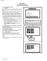
4.1.7 DISPLAY METHOD WHEN RASTER IS NOT AVAILABLE

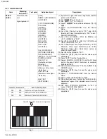
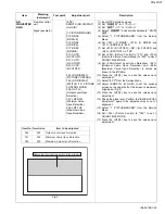
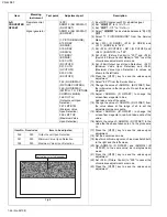
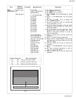
When raster is not displayed due to failure of the set, the POWER LED light will flash to indicate the ailure mode.
Trigger for forced shutdown of power is stored and displayed.

<Details on Operation>

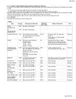
Power of TV will be turned off when NG is detected for "Panel Error" and "LOB Protection". "POWER LED" will start flashing imme-
diately after power is turned off and power of tuner and panel cannot be turned on upon shutdown until the AC plugs are discon-
nected once and reconnected. 

Item

Display

Description of detection

Diagnosis 

signal (line)

Means of detection

Unit

PANEL
TEMPERATURE

PRO

Is temperature of thermostat in 
PDP proper?

SDA

Detection starts 5 seconds upon
power on Performs detection every
16ms and turns off power if NG lasts
for 500ms

Display

PANEL
OPERATION

LVP

Is panel protection activated 
properly?

SDA

Same as above

Display

PANEL
OPERATION

ALM

Is panel protection activated 
properly?

SDA

Same as above

Display

PANEL
TEMPERATURE 
RISE

TMP

Is temperature in PDP proper?

SDA

Performs detection every 0.5 sec and 
turns off power if number of times 
temperature exceeds service setting 
beyond acceptable limit  

Display

AUDIO
TEMPERATURE

ATP

Not used (Only display)

-

-

-

Audio Terminal

AMP

Not used (Only display)

-

-

-

Memory

MEMP Is ACK returned during I

2

transmission? [IC1703]

SDA

Monitors upon every I

2

C transmission 

and counts if ACK is not returned

Display

INSIDE
TEMPERATURE 
OF A RECEIVER 
UNIT

TEMP

Is temperature in receiver proper? 
[IC505]

SDA

Turns off power if temperature in 
receiver is 73 degrees Celsius or 
higher.  

Receiver

DEVICE DRIVER 
COLOR
MANAGEMENT

DDT

Is ACK returned during I

2

transmission? [IC401]

SDA

Monitors upon every I

2

C transmission 

and counts if ACK is not returned.

Receiver

DEVICE DRIVER 
COLOR
MANAGEMENT

DDP

Same as above [IC401]

SDA

Same as above

Display

Fan

FAN

Not used (Only display)

-

-

-

A/D CONVERTER

AD

Is ACK returned during I

2

transmission? [IC001]

SDA

Monitors upon every I

2

C transmission 

and counts if ACK is not returned.

Receiver

DVI

DVI

Same as above [IC7701]

SDA

Same as above

Receiver

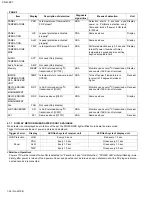
Trigger of error

Display

LED flash cycle of receiver unit

LED flash cycle of display unit

LOB Protection

LOB

Every 2.0 secs

Red every 1.0 sec

Panel

PRO

Every 1.0 sec

Green every 0.1 sec

ALM

Every 1.0 sec

Green every 1.0 sec

TMP

Every 1.0 sec

Green every 2.0 sec

Summary of Contents for pd-42dxt

Page 1: ...TELEVISION 52108 2003 01 PD 42DXT TABLE OF CONTENTS 1 PRECAUTIONS 1 3 2 SPECIFIC SERVICE INSTRUCTIONS 1 6 3 ADJUSTMENTS 1 20 4 TROUBLE SHOOTING 1 52 TS 42DXT FRONT SPEAKER R TS 42DXT FRONT SPEAKER L TS 42DXT SUB WOOFER RM C289 PD 42DXT PLASMA DISPLAY UNIT TU 42DXT RECEIVER UNIT BASIC CHASSIS SB3 ...

Page 2: ...Mini DIN4 pin x 3 Y 1V p p Positive Negative sync provided 75 ohm C 0 286V p p Burst signal 75 ohm VIDEO 1V p p Positive Negative sync provided 75 ohm RCA pin jack x 4 AUDIO 500mV rms High Impedance RCA pin jack x 8 VIDEO 3 DVD COMPONENT VIDEO IN 1125i 750p 525p 525i RCA pin jack x 3 Y 1V p p Sync signal 0 35V p p 3 value sync 75 ohm Pb Pr 0 35V p p 75 ohm Y 1V p p Positive Negative sync provided ...

Page 3: ...eplacements or alternatives approved by the manufacturer of the complete product 7 Do not check high voltage by drawing an arc Use a high voltage meter or a high voltage probe with a VTVM Discharge the picture tube before attempting meter connection by connecting a clip lead to the ground frame and connecting the other end of the lead through a 10k 2W resistor to the anode button 8 When service is...

Page 4: ...ll the unit on stable flooring or stands Take precautionary measures to prevent the unit from tipping in order to protect against accidents and earthquakes 1 2 3 FALL TIP PREVENTION MEASURES Take precautionary measures to prevent the unit from falling or tipping to protect against emergencies such as earthquakes as well as accidents Fasten the supplied hook for tip fall prevention using the screws...

Page 5: ...the case of animated images When switching to another image after continuous display of the previous image residual images may become prominent as luminance in a part of the display is higher than the other parts This is not a defect but is because due to the discharge surface of the lighted portion has becomebeing relatively activated and its luminance higher than the unlighted parts 1 5 INFRARED...

Page 6: ...is a function that is power saving and gentle to eyes Memo screen function The images that are currently seen can be viewed on the memo screen still picture It is convenient for taking down notes like application address and recipe of cooking program etc while enjoying the current program i LINK Input Output Terminal By just connecting an i Link cable to the sharing device equipped with the i Link...

Page 7: ... defects pixels that are always not lit and on the contrary pixels that are always lit exist depending on each case There are 2 types of Pixel defects Bright Dot Defects and Dark Dot Defects as defined respectively in the following 1 Bright Dot Defects Bright dot defects are pixel defects where the pixel should basically be unlit but lit or blinks The presence of bright dot defects can be confirme...

Page 8: ...sed 17 AC_IN TM5IOB I AC power supply input 18 SCL2 P42 O Not used 19 TU_POW P41 O Tuner power control 20 VCOI VCOI I LPF input 21 PDO PDO O LPF output 22 IP_RESET P80 O Reset L 23 OSD_YM DAYMOUT O YM signal output For OSD 24 OSD_B DABOUT O B signal output For OSD 25 POW_LED P77 O Power supply LED In lighting H 26 OSD_G DAGOUT O G signal output For OSD 27 OSD_R DAROUT O R signal output For OSD 28 ...

Page 9: ...POW P71 O Main power control 63 NC NC Not used 64 B1_POW P70 O Not used 65 C N ADIN4 I Not used 66 XÅ RAY ADIN3 I Not used 67 EE_CDS ADIN2 I EE sensor input 68 KEY2 ADIN1 I Key scan data input KEY2 69 KEY1 ADIN0 I Key scan data input KEY1 70 SCL1 SCL1 O I2 C bus clock For EEPROM 71 SDA1 SDA1 I O I2 C bus data For EEPROM 72 REMO RMIN IRQ0 I Remote control data input 73 AP_REQ P87 O Auto panorama re...

Page 10: ... the 4 screws F and remove the AUDIO PWB NOTE Disconnect the connectors CN60SP CN600K CN60CA CN60CE CN60CF from the AUDIO PWB It is advisable to take note of the connecting location connector number of the removed connectors 2 4 5 REMOVING THE SYSTEM POWER PWB Fig 3 Remove the REAR COVER Remove the TERMINAL COVER 1 Remove the 4 screws G and remove the SYSTEM POWER PWB NOTE Disconnect the connector...

Page 11: ...onnect the connector CN0AH and earth wire from the DISPLAY INTERFACE PWB It is advisable to take note of the connecting location connector number of the removed connectors 3 Remove the 4 screws N and 5 screws O and remove the 2 pieces of SUPPORT BRACKET BOTTOM 4 Remove the 4 screws P and remove the 2 pieces of BACK FRAME BOTTOM 5 Remove the 4 screws Q and 1 screw R and remove the 2 pieces of SUPPO...

Page 12: ... x2 P x2 S T x2 Q x2 Q R x4 U x2 N x2 O x2 P SUPPORT BRACKET BOTTOM TERMINAL BRACKET SUPPORT BRACKET BOTTOM BACK FRAME BOTTOM x2 PANEL SHIELD BACK FRAME BOTTOM SUPPORT BRACKET TOP PDP UNIT FRONT PANEL INNER CASE FRONT FILTER TOP GAS insertion hole ...

Page 13: ...to impose shock to it 2 4 11 REMOVING THE DISPLAY LED PWB Fig 6 Remove the INNER CASE 1 Remove the 2 screws X and remove the DISPLAY LED PWB 2 4 12 REMOVING THE PANEL SW PWB Fig 6 Remove the INNER CASE 1 Remove the 2 screws Y and remove the CONTROL BASE 2 Remove the 3 screws Z and remove the DISPLAY SW PWB 2 4 13 REMOVING THE FRONT FILTER Fig 6 Remove the INNER CASE 1 Remove the 10 screws a and re...

Page 14: ...screws N and 2 screws O and with draw the display output terminal 6 Remove the 7 screws P and withdraw the video audio terminal 7 Withdraw the REAR COVER in a rear direction 2 5 6 REMOVING THE DET MODULE PWB AND DET RELAY PWB Remove the TOP COVER Remove the FRONT PANEL Remove the FRONT CONTROL PWB Remove the REAR COVER 1 Remove the 2 screws T 2 screws U and 2 screws V and lift upwards and withdraw...

Page 15: ...OOK G b Claw CONNECTOR TOP COVER CHASSIS BRACKET FRONT PANEL SUB TUNER PWB FRONT CONTROL PWB FRONT PANEL FRONT DOOR DET RELAY PWB MI COM DET MODULE PWB MAIN PWB RECEIVER POWER PWB COOLING FAN BRACKET COOLING FAN BOTTOM CASE BACK COVER P L M x2 x7 O x2 N x2 J x2 K x1 H H FRONT PANEL BACK SIDE AC INLET Q d c H DAMPER SD CARD PWB BS HOLDER ...

Page 16: ...MENT section Serviceman setting items MAIN MENU SCREEN MAIN MENU SCREEN 1 PICTURE SOUND 2 YC SEP 3 WHITE BALANCE 4 MEMORY SETUP 5 DD CM 6 ߎߩࠝࡦࠬࠢ ࡦ ਛߪࡏ ࡦࠍ ߐߥ ߢਅߐ ޕ 7 PANEL 8 PP 9 IP 10 GCR SERVICEMAN SETTING MODE SERVICEMAN SETTING MODE This is a message for users Ignore this message when in the Service Menu mode Setting Items Settings Item No 1 PICTURE SOUND sound and picture setting Sound circuit...

Page 17: ...ネル 1 画面サイズ ノーマル 音量 適切な音量位置 オフタイマー 切り 解除 消音 切り 映像選択 スタンダード 画面表示 表示なし 映画 切り 機器ナビ 機器操作 ナチュラルシネマ オート 音声切換 モノラル PICTURE MODE ピクチャー PICTURE 黒レベル BRIGHT 色の濃さ COLOR 色あい TINT シャープネス SHARP 白バランス W BALANCE ノイズクリア NOISE CLEAR ダイナミック 00 00 12 00 00 高い色温度 切り スタンダード 00 00 00 00 00 低い色温度 切り ゲーム 10 00 00 00 00 高い色温度 切り シアターステータス 00 00 00 00 00 高い色温度 切り シアタープロ DSD エッジ シャープネス DSD コアリング 速度変調 白バラ赤 白バラ青 色バランス H V 00 00...

Page 18: ...センター位置 デジタル E E 入り デジタル E E の効果表示 Do not display 無信号電源オートオフ Do not set S N 連動 切り テレビ消し忘れ防止設定 Do not set オートパノラマ動作時の画面 ノーマル画面 ビデオ 1 入力端子信号のモニター出力 No output AV コンピュリンクⅢ端子 Not use Setting items Settings チャンネル 入力設定の変更 見るチャンネル Receiving remote control channel key 画面の表示 Displaying remote control channel key ボタン 見る GRT ゴースト低減 入り 受像微調整 00 CATV 選局方式の選択 12 ボタン方式 スクリーンセーバーの設定 Not set 画面シフト 標準 Position 1 2 3 ...

Page 19: ...ith the tweezers and remove the chip part Transistors diodes variable resistors etc 1 Apply extra solder to each lead 2 As shown in the figure push the part with tweezers and alternately melt the solder at each lead Shift and remove the chip part NOTE After removing the part remove remaining solder from the pattern 2 How to install Chip parts Resistors capacitors etc 1 Apply solder to the pattern ...

Page 20: ... values on the service screen that are not stated in this manual 6 Unless otherwise stated in the Adjustment Procedure section follow the settings for the features stated below using the remote control 3 2 MEASURING INSTRUMENT AND FIXTURES DC voltmeter or Digital voltmeter Oscilloscope Signal generator Pattern generator Remote control unit 3 3 MAIN PARTS LOCATIONS RECEIVER UNIT Setting item Settin...

Page 21: ...S BASE P CA J K PW F901 L F PWB AH SP CB CD CC CE CE SP CF CA K CB J P AT AV AU AV C2 C1 NC CF NC DISPLAY SW PWB AUDIO PWB SYSTEM POWER PWB PDP POWER PWB DISPLAY INTERFACE PWB SPEAKER TERMINAL PWB CN301 CN302 PDP UNIT PDP UNIT C4 POWER CONNECTOR CN0C4 DISPLAY LED PWB TOP CN104 PDP UNIT ...

Page 22: ...㨪ADM034 PPA001㨪PPA008 PPB001㨪PPB036 PPC001㨪PPC008 PPD001㨪PPD025 DDT01㨪DDT34 CMT01㨪CMT57 DDP01㨪DDP37 CMP01㨪CMP03 PDA001 IN OUT TEM APL MIN MAX PDA001㨪PDA012 A01㨪A27 S01㨪S99 D01㨪D32 F01㨪F59 10 GCR GCR01㨪GCR08 S01 D01 F01 NTSC FULL ST L FL MUTE YCM001㨪YCM185 YCS001㨪YCS114 NTSC FULL ST L FL MUTE GCR01 00001000 NTSC FULL ST L FL MUTE ࠕ ࠬ 㧜 㧝 㧞 㧟 㧠 㧡 㧢 㧣 㧤 㧥 㧭 㧮 㧯 㧰 㧱 㧲 2 YC SEP 7 PANEL 8 PP 4 MEMORY SE...

Page 23: ... key 7 Press the 消音 key to save the value NOTE Ensure that the items are set as follows before entering the Service Menu mode 3 6 2 HOW TO EXIT THE SERVICE MENU MODE Press the メニュー key to exit the Service Menu mode 3 6 3 SERVICE CONTROL KEY LAYOUT ON THE REMOTE CONTROL オートパノラマ 使用しない 映画ボタン 切 USER MENU SCREEN 映像調節 MAIN MENU MAIN MENU 1 PICTURE SOUND 2 YC SEP 3 WHITE BALANCE 4 MEMORY SETUP 5 DD CM 6 ...

Page 24: ...he item codes 音量 key For scrolling up down the data values 3 6 4 3 3 WHITE BALANCE White Balance setting Setting for this item is not required in servicing 3 6 4 4 4 MEMORY SETUP Memory setting Do not change settings 3 6 4 5 5 DD CM Do not change settings of items that are not included in the ADJUSTMENT PROCEDURE section チャンネル key For scrolling up down the item codes 音量 key For scrolling up down t...

Page 25: ...ues by adding offset values to the base values Base values are displayed as 3 7 1 1 PICTURE SOUND Item No Item Variable range Setting value A01 NO DISPLAY 000 007 003 A02 NO DISPLAY 000 007 003 A03 NO DISPLAY 000 007 003 A04 NO DISPLAY 000 007 004 A05 NO DISPLAY 000 015 009 A06 NO DISPLAY 000 015 006 A07 NO DISPLAY 000 015 006 A08 NO DISPLAY 000 015 003 A09 NO DISPLAY 000 007 006 A10 NO DISPLAY 00...

Page 26: ...ting value 525p 750p 1125i スタンダード シアター スタンダード シアター 高 低 高 低 高 低 高 低 S13 RDRV 000 255 255 255 255 255 255 255 255 255 S14 RDRV 127 128 028 000 000 000 028 000 000 000 S15 GDRV 000 255 255 255 255 255 255 255 255 255 S16 GDRV 127 128 016 000 003 016 016 000 003 016 S17 BDRV 000 255 255 255 255 255 255 255 255 255 S18 BDRV 127 128 000 000 017 032 000 000 017 032 Item No Item Variable range Setting val...

Page 27: ...0 063 063 063 063 060 060 S40 WKAKON 000 001 001 001 001 001 001 001 000 001 S41 WGAINC 000 001 000 001 001 001 001 001 000 001 S42 GAINB 000 003 001 000 003 000 003 000 001 000 S43 SLIC 000 031 011 011 013 019 013 019 011 011 S44 APG 000 003 001 002 001 003 001 003 001 002 S45 GAINA 000 003 001 001 001 001 001 001 002 001 Item No Item Variable range Setting value スタンダード シアター S46 NOT USED 000 015 ...

Page 28: ...03 S68 CLIP 000 015 000 000 000 000 000 000 000 000 S69 COR 000 063 019 019 019 019 019 019 019 019 Item No Item Variable range Setting value S70 TINTON 001 001 001 S71 DRIVER 001 255 255 S72 DRIVEG 001 255 255 S73 DRIVEB 001 255 255 Item No Item Variable range Setting value S74 EECONT 001 031 018 S75 EEBRT 001 031 031 Item No Item Variable range Setting value NTSC 525i 525p 750 1125i S76 EETBRT 1...

Page 29: ...008 008 006 S97 DCLIM 001 063 030 025 030 025 030 025 025 025 S98 NO DISPLAY 001 001 000 000 000 000 000 000 000 000 S99 NO DISPLAY 001 001 000 000 000 000 000 000 000 000 Item No Item Variable range Setting value F01 NO DISPLAY 000 255 000 F02 NO DISPLAY 000 255 000 F03 NO DISPLAY 000 255 000 F04 NO DISPLAY 000 255 032 F05 NO DISPLAY 000 001 000 F06 CATVMAX 000 001 001 F07 NO DISPLAY 000 255 150 ...

Page 30: ...01 000 F32 NO DISPLAY 000 001 000 F33 NO DISPLAY 000 001 000 F34 NO DISPLAY 000 001 000 F35 NO DISPLAY 000 001 000 F36 NO DISPLAY 000 001 000 F37 NO DISPLAY 000 001 000 F38 NO DISPLAY 000 001 000 F39 NO DISPLAY 000 001 000 F40 NO DISPLAY 000 001 000 Item No Item Variable range Setting value NTSC 525i 525p 750p 1125i F41 NO DISPLAY 000 003 000 000 000 000 000 F42 NO DISPLAY 000 001 000 000 000 000 ...

Page 31: ... DISPLAY 000 001 NOT USED F55 NO DISPLAY 000 001 NOT USED F56 NO DISPLAY 000 001 NOT USED F57 NO DISPLAY 000 001 NOT USED F58 NO DISPLAY 000 001 NOT USED F59 NO DISPLAY 000 001 NOT USED F60 NO DISPLAY 000 001 NOT USED F61 NO DISPLAY 000 001 NOT USED F62 NO DISPLAY 000 001 NOT USED F63 NO DISPLAY 000 001 NOT USED F64 NO DISPLAY 000 001 NOT USED F65 NO DISPLAY 000 001 NOT USED F66 NO DISPLAY 000 001...

Page 32: ...000 YCM035 NO DISPLAY 000 255 096 YCM036 NO DISPLAY 000 001 001 YCM037 NO DISPLAY 000 003 001 YCM038 NO DISPLAY 000 127 062 YCM039 NO DISPLAY 000 127 068 YCM040 NO DISPLAY 000 003 002 YCM041 NO DISPLAY 000 063 016 YCM042 NO DISPLAY 000 001 000 YCM043 NO DISPLAY 000 001 000 YCM044 NO DISPLAY 000 255 182 YCM045 NO DISPLAY 000 001 000 YCM046 NO DISPLAY 000 255 127 YCM047 NO DISPLAY 000 001 001 YCM048...

Page 33: ...00 255 002 YCM126 NO DISPLAY 000 001 000 YCM127 NO DISPLAY 000 001 001 Item No Item Variable range Setting value YCM128 NO DISPLAY 000 001 001 YCM129 NO DISPLAY 000 001 001 YCM130 NO DISPLAY 000 003 001 YCM131 NO DISPLAY 000 255 050 YCM132 NO DISPLAY 000 255 131 YCM133 NO DISPLAY 000 255 055 YCM134 NO DISPLAY 000 007 001 YCM135 NO DISPLAY 000 255 136 YCM136 NO DISPLAY 000 001 000 YCM137 NO DISPLAY...

Page 34: ...3 YCS029 NO DISPLAY 000 007 006 YCS030 NO DISPLAY 000 003 003 Item No Item Variable range Setting value YCS031 NO DISPLAY 000 001 000 YCS032 NO DISPLAY 000 003 003 YCS033 NO DISPLAY 000 001 001 YCS034 NO DISPLAY 000 001 000 YCS035 NO DISPLAY 000 255 096 YCS036 NO DISPLAY 000 001 001 YCS037 NO DISPLAY 000 003 001 YCS038 NO DISPLAY 000 127 062 YCS039 NO DISPLAY 000 127 068 YCS040 NO DISPLAY 000 003 ...

Page 35: ...3 001 YCS111 NO DISPLAY 000 003 001 YCS112 NO DISPLAY 000 003 001 YCS113 NO DISPLAY 000 003 001 YCS114 NO DISPLAY 000 255 000 Item No Item Variable range Setting value Input signal NTSC Screen size フルモード Multi screen Single screen Picture selection スタンダード White balance 低い色温度 Item No Item Variable range Setting value BR NO DISPLAY 00000 238 111 DRV R NO DISPLAY 00000 255 130 DRV B NO DISPLAY 00000 ...

Page 36: ...DISPLAY 128 127 020 CMT037 NO DISPLAY 000 255 064 CMT038 NO DISPLAY 000 255 064 Item No Item Variable range Setting value CMT039 NO DISPLAY 000 255 088 CMT040 NO DISPLAY 128 127 000 CMT041 NO DISPLAY 128 127 010 CMT042 NO DISPLAY 000 001 000 CMT043 NO DISPLAY 000 255 128 CMT044 NO DISPLAY 000 001 001 CMT045 NO DISPLAY 000 255 000 CMT046 NO DISPLAY 000 001 000 CMT047 NO DISPLAY 000 255 128 CMT048 N...

Page 37: ...PDA012 NO DISPLAY 000 127 000 Item No Item Variable range Setting value Input signal NTSC Screen size フルモード Multi screen Single screen Picture selection スタンダード White balance 低い色温度 Item No Item Variable range Setting value ADM001 NO DISPLAY 000 0FF 0D6 ADM002 NO DISPLAY 000 00F 007 ADM003 NO DISPLAY 000 003 001 ADM004 NO DISPLAY 000 007 005 ADM005 NO DISPLAY 000 01F 016 ADM006 NO DISPLAY 000 0FF 03...

Page 38: ...4 PPB026 NO DISPLAY 000 255 160 PPB027 NO DISPLAY 000 255 000 PPB028 NO DISPLAY 000 031 224 PPB029 NO DISPLAY 000 255 160 PPB030 NO DISPLAY 000 255 020 PPB031 NO DISPLAY 000 031 224 PPB032 NO DISPLAY 000 255 160 PPB033 NO DISPLAY 000 255 040 PPB034 NO DISPLAY 000 031 224 PPB035 NO DISPLAY 000 255 160 PPB036 NO DISPLAY 000 255 060 Item No Item Variable range Setting value PPC001 NO DISPLAY 000 015 ...

Page 39: ...00 IPA035 NO DISPLAY 000 001 077 IPA036 NO DISPLAY 000 063 000 IPA037 NO DISPLAY 000 063 013 IPA038 NO DISPLAY 000 063 016 IPA039 NO DISPLAY 000 003 095 IPA040 NO DISPLAY 000 003 000 IPA041 NO DISPLAY 000 015 000 IPA042 NO DISPLAY 000 063 005 IPA043 NO DISPLAY 000 063 008 IPA044 NO DISPLAY 000 063 012 IPA045 NO DISPLAY 000 063 012 IPA046 NO DISPLAY 000 063 012 IPA047 NO DISPLAY 000 003 095 IPA048 ...

Page 40: ...0 IPB005 NO DISPLAY 000 015 033 IPB006 NO DISPLAY 000 255 000 Item No Item Variable range Setting value IPB007 NO DISPLAY 000 015 000 IPB008 NO DISPLAY 000 255 160 IPB009 NO DISPLAY 000 015 017 IPB010 NO DISPLAY 000 255 000 IPB011 NO DISPLAY 000 015 000 IPB012 NO DISPLAY 000 255 192 IPB013 NO DISPLAY 000 015 000 IPB014 NO DISPLAY 000 255 000 IPB015 NO DISPLAY 000 015 000 IPB016 NO DISPLAY 000 255 ...

Page 41: ... 000 003 000 IPC014 NO DISPLAY 000 001 000 IPC015 NO DISPLAY 000 001 128 Item No Item Variable range Setting value IPC016 NO DISPLAY 000 255 000 IPC017 NO DISPLAY 000 001 000 IPC018 NO DISPLAY 000 127 000 IPC019 NO DISPLAY 000 001 000 IPC020 NO DISPLAY 000 127 000 IPC021 NO DISPLAY 000 015 000 IPC022 NO DISPLAY 000 255 010 IPC023 NO DISPLAY 000 003 001 IPC024 NO DISPLAY 000 255 056 IPC025 NO DISPL...

Page 42: ... 000 255 001 IPE003 NO DISPLAY 000 255 001 IPE004 NO DISPLAY 000 255 002 IPE005 NO DISPLAY 000 255 001 IPE006 NO DISPLAY 000 255 002 IPE007 NO DISPLAY 000 255 001 IPE008 NO DISPLAY 000 255 002 IPE009 NO DISPLAY 128 127 005 IPE010 NO DISPLAY 128 127 006 IPE011 NO DISPLAY 128 127 005 IPE012 NO DISPLAY 128 127 005 IPE013 NO DISPLAY 128 127 251 IPE014 NO DISPLAY 128 127 005 IPE015 NO DISPLAY 000 015 0...

Page 43: ...re that the voltage between Pins 5 and 6 of CN0C4 5V coincides with the values in the table 5 Turn off the power and connect the CN0AT and CN0AU connectors and turn on the power again 6 Input the NTSC 525i all black signal and check that it coincides with the Values in the table 7 If the adjusted value is different from those in the table fine tune without unplugging the connectors CAUTION Designa...

Page 44: ...nd S17 B DRIVE to 255 8 Set S19 R CUTOFF S21 G CUTOFF and S23 B CUTOFF to 125 9 Set F46 Output Level Upon Detection F47 Minimum Value Upon Detection and F48 Maximum Value Upon Detection to values as shown in the left table 10 Set S84 Test Mode to 003 11 Press the 消音 key to save the values upon adjustment 12 Select 8 PP from the Service Menu 13 Adjust ADM013 G OFFSET to set the 0 black part on the ...

Page 45: ...44 Picture Control to 001 and F45 Switch to Picture Control Mode to 000 to Set Y ADJUST MAX MODE 9 Set F46 Output Level Upon Detection F47 Minimum Value Upon Detection and F48 Maximum Value Upon Detection to values as shown in the left table 10 Press the 消音 key to save the values upon adjustment 11 Select 8 PP from the Service Menu 12 Adjust ADM010 G GAIN to set the window screen on the upper half...

Page 46: ...n in the left table 10 Press the 消音 key to save the values upon adjustment 11 Select 8 PP from the Service Menu 12 Change the value of ADM014 B OFFSET from the initial value in the range of 5 to set the screen magenta 13 Adjust ADM012 R OFFSET to change the screen from magenta to blue And take a note of the value 14 Change the value of ADM012 R OFFSET from the value above at the range of 5 to set ...

Page 47: ...F S21 G CUTOFF and S23 B CUTOFF to 125 8 Set F44 Picture Control to 001 and F45 Switch to Picture Control Mode to 000 to set Y DJUST MAX MODE 9 Set F46 Output Level Upon Detection F47 Minimum Value Upon Detection and F48 Maximum Value Upon Detection to values as shown in the left table 10 Press the 消音 key to save the values upon adjustment 11 Select 2 YC SEP from the Service Menu 12 Adjust YCM131 ...

Page 48: ... 7 Set S19 R CUTOFF S21 G CUTOFF and S23 B CUTOFF to 125 8 Set F44 PICTURE CONTROL to 001 and F45 Switch to Picture Control Mode to 000 to set Y ADJUST MAX MODE 9 Set F46 Output Level Upon Detection F47 Minimum Value Upon Detection and F48 Maximum Value Upon Detection to values as shown in the left table 10 Press the 消音 key to save the values upon adjustment 11 Select 2 YC SEP from the Service Men...

Page 49: ...VE S15 G DRIVE and S17 B DRIVE to 255 8 Set S19 R CUTOFF S21 G CUTOFF and S23 B CUTOFF to 125 9 Set F44 PICTURE CONTROL to 001 and F45 Switch to Picture Control Mode to 000 to set Y ADJUST MAX MODE 10 Set F46 Output Level Upon Detection F47 Minimum Value Upon Detection and F48 Maximum Value Upon Detection to values as shown in the left table 11 Press the 消音 key to save the values upon adjustment 1...

Page 50: ...UTOFF and S23 B CUTOFF to 125 9 Set F44 PICTURE CONTROL to 001 and F45 SWITCH TO PICTURE CONTROL MODE to 000 to set Y ADJUST MAX mode 10 Set F46 Output Level Upon Detection F47 Minimum Value Upon Detection and F48 Maximum Value Upon Detection to values as shown in the left table 11 Press the 消音 key to save the values upon adjustment 12 Select 8 PP from the Service Menu 13 Adjust ADM010 G OFFSET so...

Page 51: ...TURE SOUND F49 NO DISPLAY OSD G OFFSET F50 NO DISPLAY OSD B OFFSET F51 NO DISPLAY OSD R OFFSET 1 Input a picture whose signal synchronization state is stable 2 Set 映像選択 to スタンダード 3 Set 画面サイズ to フルモード 4 Select 映像調節 and set white balance to 低い色 温度 5 Set DDT01 Switch to Picture Control Mode to 001 to set OSD adjustment mode 6 Adjust F49 OSD G OFFSET F50 OSD B OFFSET and F51 OSD R OFFSET so that OSD b...

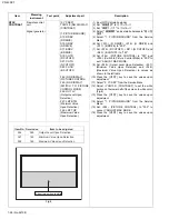
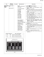
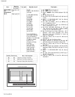
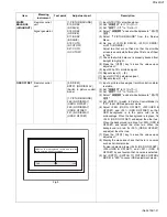
Page 52: ...F DIAGNOSIS DISPLAY MODE To Save Failure History Turn off the power by unplugging the AC power cord plug when in the self diagnosis display mode To Clear Reset Failure History Turn off the power by pressing the Power key on the remote control unit when in the self diagnosis display mode 4 1 4 FAILURE HISTORY Failure history can be counted up to 9 times for each item When the number exceeds 9 displ...

Page 53: ...s 3 seconds upon power on Turns off power if NG is detected within 200ms Receiver TIMER TIM Did power supply frequency fluctuated from 50Hz 60Hz 60Hz 50Hz Number of counts AC Regularly detects power supply frequency bv AC pulse counts and monitors frequency fluctuations other than instances immediately after reset Receiver WITH WITHOUT SYNCHRONIZED SIGNALS SYNC Are there synchronized signals HD Co...

Page 54: ...ection every 0 5 sec and turns off power if number of times temperature exceeds service setting beyond acceptable limit Display AUDIO TEMPERATURE ATP Not used Only display Audio Terminal AMP Not used Only display Memory MEMP Is ACK returned during I2 C transmission IC1703 SDA Monitors upon every I2 C transmission and counts if ACK is not returned Display INSIDE TEMPERATURE OF A RECEIVER UNIT TEMP ...

Page 55: ...PD 42DXT No 52108 1 55 ...

Page 56: ... No 52108 AV MULTIMEDIA COMPANY DISPLAY CATEGORY 12 3 chome Moriya cho kanagawa ku Yokohama kanagawa prefecture 221 8528 Japan VICTOR COMPANY OF JAPAN LIMITED 200301WPC Printed in Japan PD 42DXT ...

Reviews: