


1-18 (No.YA711<Rev.002>)
4.9.2 LCD TV SECTION
4.9.2.1
EQUIPMENT REQUIRED
a. USB memory
b. Remote Control Unit
4.9.2.2
FIRMWARE UPDATE PROCEDURE
NOTE:
There are two states (the User Upgrade and the Factory Up-
grade) in firmware update.
The identification of User Upgrade and Factory Upgrade are
done by the filename.
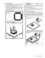
(1) Turn the power off and unplug the AC Cord.
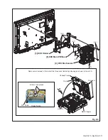
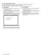
(2) Insert the USB memory to the USB port as shown below.
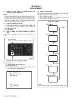
(3) Plug the AC cord in the wall outlet and turn the power on.
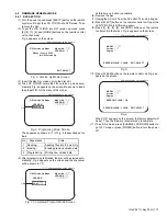
(4) The update will start and the following will appear on the
screen.
NOTE:
If the above screen isn’t displayed, repeat from step 1.
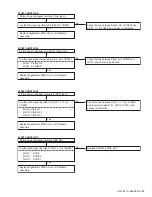
The appearance shown in *1 is described as follows.
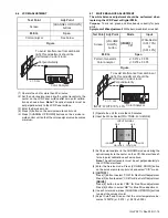
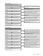
(5) When the firmware update is completed, the following will
appear on the screen.
Unplug the AC cord and kindly remove the USB memory
from the USB port. Plug the AC cord in the wall outlet again
and turn the power on.
NOTE:
When the Factory Upgrade is used, after restarting TV,
shift to initial screen menu in service mode. "INITIAL-
IZED" will appear on the upper right of the screen. "INI-
TIALIZED" color will change to green from red when
initializing is complete.
User Upgrade
Upgrade the firmware only. The
setting values are not initialized.
Factory upgrade
Upgrade the firmware and initialize
the setting values.
Rear Cabinet
USB Memory
USB port
Software upgrade in progress. Please wait.
Do not remove the USB device or turn the TV off
while upgrade is in progress.
Software Upgrade
Downloading...
0%
*1
Appearance
State
Downloading...
Downloading the firmware from the USB
memory.
Writing...
Writing the downloaded firmware in flash
memory.
Checking...
Checking the new firmware.
Software Upgrade
The software upgrade is completed.
Remove USB storage device, unplug and replug power code.
Summary of Contents for LT19D200 - 19" LCD TV
Page 10: ...1 10 No YA711 Rev 002 2 Rear Cabinet S 1 1 Stand Assembly S 2 S 4 S 2 S 2 S 3 Fig D1 ...
Page 70: ...2 54 No YA711 Rev 001 No YA711 Rev 001 2 53 TOP PATTERN DIAGRAMS MAIN PWB PATTERN SOLDER SIDE ...
Page 71: ... No YA711 Rev 001 2 55 2 56 No YA711 Rev 001 R699 TOP MAIN PWB PATTERN PARTS SIDE ...


