background image

11

Preparation

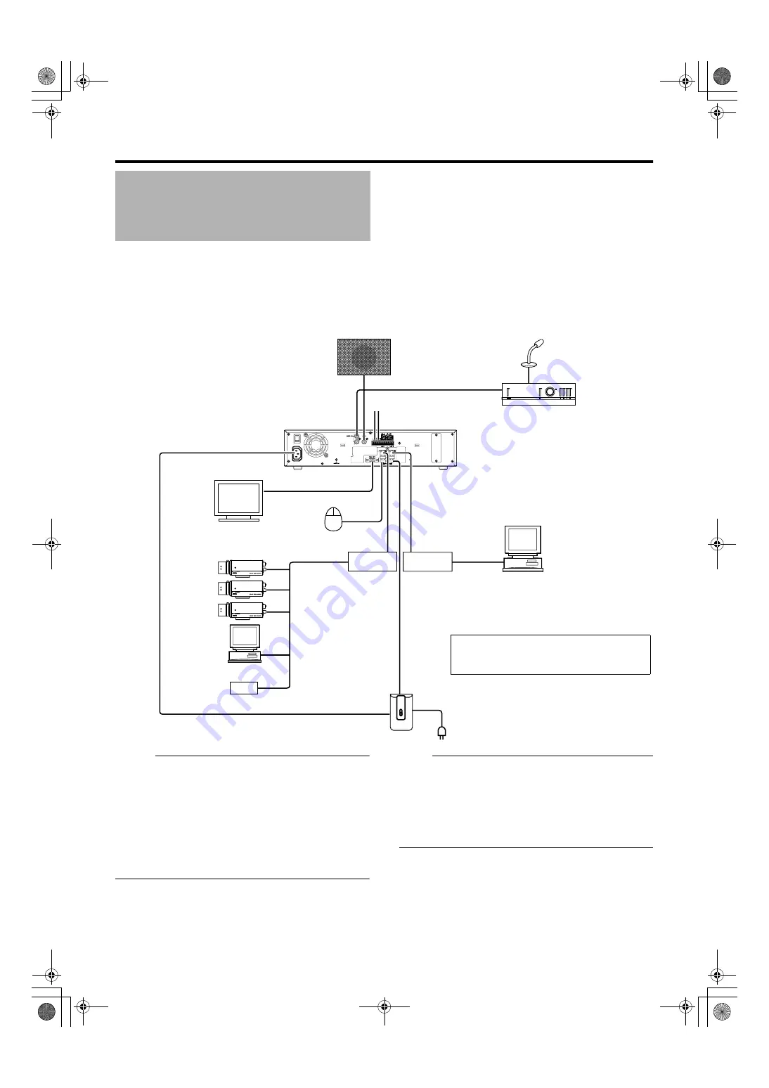
The following operations are possible with this system.

Surveillance (live image, recording and playback) by connecting up to 16 cameras

Checking recorded images on the VGA monitor

Recording/Playing sound

Alarm recording

Remote surveillance using PCs

Memo :                                                                                 

Connect LAN1 to the camera network.

LAN2 to the surveillance computer network.

For details of the protocol and port number for the network 
cameras on the LAN1 network, refer to the network 
camera’s user manual.

The protocol and port number used on the LAN2 network 
are shown below.

Surveillance computer: HTTP 80

Mail: SMTP 25/POP 110


Connect NAS to the LAN1 network.

Note :                                                                                

Connect only after having turned 

A

OFF

B

 the power of all 

devices.

Set the IP address of the camera to 192.168.0.xxx. When 
setting the IP address of the camera to an address other 
than 192.168.0.xxx, you must also change the IP address 
of LAN1. Refer to the [Instruction Manual] of each camera 


for procedures to change the camera’s IP address,

System Connection 
Example

ON

OFF

AUDIO IN

AUDIO OUT

ALARM IN/ALARM OUT

VGA OUT

S

ERIAL

LAN1

LAN2

S

ERIAL

You can connect up to 16 cameras.

You can connect up to 10 surveillance 
computers.

Speaker (with built-in amplifier)

ALARM IN/OUT

Supplied power cable

Mic Amp

VGA monitor

IP cameras

Computer for configuring 
cameras

USB Mouse

Switching

HUB

Switching

HUB

UPS control

UPS

Microphone

Surveillance computer

NAS

VR-N1600_Startup_EN_001B.book  Page 11  Thursday, August 20, 2009  1:10 PM

Summary of Contents for LST0601-001B

Page 1: ...TWORK VIDEO RECORDER STARTUP GUIDE A Please read the following before getting started Thank you for purchasing this JVC product Before operating this unit please read the instructions carefully to ensure the best possible performance For Customer Use Enter below the Serial No which is located on the body Retain this information for future reference Model No VR N1600U Serial No VR N1600_Startup_EN_...

Page 2: ...IMPORTANT SAFEGUARDS I VR N1600_Startup_EN_001B book Page I Thursday August 20 2009 1 10 PM ...

Page 3: ...SAFETY PRECAUTIONS for USA II VR N1600_Startup_EN_001B book Page II Thursday August 20 2009 1 10 PM ...

Page 4: ...SAFETY PRECAUTIONS for Europe III VR N1600_Startup_EN_001B book Page III Thursday August 20 2009 1 10 PM ...

Page 5: ...IV VR N1600_Startup_EN_001B book Page IV Thursday August 20 2009 1 10 PM ...

Page 6: ...SICHERHEITSVORKEHRUNGEN for Germany V VR N1600_Startup_EN_001B book Page V Thursday August 20 2009 1 10 PM ...

Page 7: ...VI VR N1600_Startup_EN_001B book Page VI Thursday August 20 2009 1 10 PM ...

Page 8: ...SICHERHEITSVORKEHRUNGEN for Germany VII VR N1600_Startup_EN_001B book Page VII Thursday August 20 2009 1 10 PM ...

Page 9: ...VIII E 1600E E 1600E E E VR N1600_Startup_EN_001B book Page VIII Thursday August 20 2009 1 10 PM ...

Page 10: ...otionB is detected in the preset live image You can also specify the detection area for each camera Alarm Mail Notification Enables notification by e mails to be sent out when an alarm or motion is detected Features How to Read this Manual 䡵 VR N1600U E Documents There are two documents on this unit 1 Startup Guide This is a booklet that is supplied together with VR N1600U E It is also available i...

Page 11: ... Control 16 Displaying the Live Screen 16 Select a View 16 Select a Camera 16 Operating the Camera 17 Playing Back Recorded Images via Front Panel Control 18 Select a View 18 Searching Recorded Image Using a Specific Date Time 18 Playing Skipping and Stopping Recorded Images 18 Adjusting the Playback Speed Jog Shuttle Playback 19 Others Troubleshooting 20 Specifications 21 Contents VR N1600_Startu...

Page 12: ... distance between the head and the disk is only about 0 02 μm when the hard disk henceforth HDD is reading the data Vibration or impact that is exerted on the HDD may therefore cause the head to hit against the disk hence causing the disk surface to dent or the disk to chip When this occurs data may not be properly read or in a worse scenario continued use in this condition may result in head cras...

Page 13: ...n infringement of the copyrights of their respective authors under the copyright law 䢇 These video audio recordings shall only be restricted to personal uses and their use without prior consent of the copyright holder is strictly prohibited under the copyright law Others 䢇 When there is variation in the supply voltage such as during lightning operation of this unit may be disabled to protect the s...

Page 14: ...ator Lights up when an error occurs A Page 20 Press and hold the ALARM CLEAR button to turn off the light 䡵 ALARM Indicator Lights up when an alarm is activated Goes off when the ALARM CLEAR button is pressed 䡵 HDD Indicator Lights up when the built in hard disk drive is accessed 䡵 LOCK Indicator Lights up when operation is locked G FUNCTION Button Press the following buttons while holding down th...

Page 15: ...lecting a camera number Upon selecting the indicator corresponding to the selected camera input lights up PTZ keypad mode live image display screen only Moves the camera in the direction indicated by the arrow 1 2 D 3 5 C 7 B 9 10 0 E 11 Use the 6 HOME button to move the camera to the home position Preset keypad mode live image display screen only For selecting the preset position 1 to 9 10 to 19 ...

Page 16: ...ting the communication control terminals on a mouse sold separately flash memory sold separately UPS sold separately or additional disk drive sold separately b LAN2 LAN2 connection terminal Intranet For connecting to the remote PC network using a LAN cable c Connector cover Memo Do not remove the cover d Signal input output terminals For operating VR N1600U E using external alarm signals or signal...

Page 17: ...signal is input 䡵 Output ports j COMMON signal ground terminal This is a common ground terminal Connect it to the signal ground terminal on the connected device This can be used when there are insufficient common ground terminals k ALARM OUT alarm output terminal Outputs a signal when recording is started by an alarm l WARNING OUT warning output terminal Outputs a signal when an error such as oper...

Page 18: ...e ALARM IN Memo Set the impedance at the output end to 10kK or below Make Contact Input f EMER GENCY g ALARM RESET Memo Set the impedance at the output end to 10kK or below Make Contact Input h EXT REC IN Memo Set the impedance at the output end to 10kK or below Make Contact Input j OPE ON OFF Memo Set the impedance at the output end to 10kK or below Make Contact Input j REC TALLY k ALARM OUT l WA...

Page 19: ...etwork Note Connect only after having turned AOFFB the power of all devices Set the IP address of the camera to 192 168 0 xxx When setting the IP address of the camera to an address other than 192 168 0 xxx you must also change the IP address of LAN1 Refer to the Instruction Manual of each camera for procedures to change the camera s IP address System Connection Example ON OFF AUDIO IN AUDIO OUT A...

Page 20: ...commended that a single VR N1600U E be used for registering one IP camera as well as for controlling PTZ operations Do not connect a broken hub router or deteriorated network cable etc Doing so may prevent the system from operating properly Connection to a keyboard is not recommended Perform language setting and automatic camera registration when starting up VR N1600U E for the first time Start up...

Page 21: ...a list of detected cameras is displayed If all the cameras are not detected press the Auto Detect button again If doing so does not solve the problem check the connection with the cameras and the IP address of the cameras Memo Devices other than the cameras may appear in the list Uncheck the boxes of these devices 3 Swap the order of detected cameras Select SORT button using SKIP button and press ...

Page 22: ...rate of all cameras does not exceed 80 ips VR N1600U E or 160 ips VR N1600U E A The default display rate is set at 8 ips The maximum display performance of 80 ips will be exceeded if 11 or more cameras are detected In this case you will need to adjust the display rate of each camera using the following steps VR N1600U E Note The recording rate may drop if the total display rate of all cameras exce...

Page 23: ...Memo Use SKIP to move between the items Use the 2 D and 10 0 E buttons to select the item to configure To enter numeric characters press the SELECT button to turn on the light of the SELECT indicator Upon entering the numeric characters press the PTZ PRESET button to turn on the light of the PTZ PRESET indicator G Use the SKIP button to select OK followed by pressing the 16 ENTER button 11 Repeat ...

Page 24: ...t the password on the camera unit as well as VR N1600U E again For details on the setting procedures refer to the INSTRUCRTIONS of the camera in use and procedures for setting the root password on the Edit device settings screen in this manual The audio setting is set to ANo Audio SourcesB when you return from the setting screen to Live Select the audio parameters again Select a Camera Select the ...

Page 25: ... direction indicated by the arrow on the keys Press the 6 HOME key to move to the home position 䡵 Zoom In Zoom Out 1 Press the PTZ PRESET button to switch the keypad to the PTZ mode The PTZ PRESET indicator lights up Press the button to switch between the APTZ ModeB indicator lights up and APreset ModeB indicator blinking 2 Press the 15 ZOOM IN or 14 ZOOM OUT button 䡵 Using Preset Positions 1 Pres...

Page 26: ...u return from the setting screen to Browse Select the audio parameters again Searching Recorded Image Using a Specific Date Time You can search for and play back images by specifying a date and time using the SEARCH button on the front panel 1 Press the SEARCH button on the Browse screen The date and time input screen appears 2 Use the keypad to enter the search date and time Use the SKIP button S...

Page 27: ...speed that is indicated during fast forward or fast reverse playback by rotating the shuttle dial is an approximate value The speed may differ depending on the conditions such as the playback mode multi view single view and the recording mode motion detection recorded frame rate 䡵 Jog Playback Rotate the jog dial to play back frame by frame Rotate the dial clockwise to play back a single frame in ...

Page 28: ...power forcibly When the power is forcibly shut down recorded images that are not archived may not be properly played back The following message appears after the power is turned on ACOMS Settings Wrong CMOS Date Time Not Press F1 to Run SETUP Press F2 to load default values and continueB The built in backup battery is low Consult your nearest JVC dealer Error Message Action to Take Free space of H...

Page 29: ... E A When not viewing live images on NVR Up to 240 ips 0 ips 80 ips VR N1600U E Up to 240 ips 0 ips 160 ips VR N1600U E A When NVR Viewer is not started up When using NAS When viewing live images on NVR Up to 80 ips 80 ips 80 ips VR N1600U E Up to 80 ips 160 ips 160 ips VR N1600U E A When not viewing live images on NVR Up to 80 ips 0 ips 80 ips VR N1600U E Up to 80 ips 0 ips 160 ips VR N1600U E A ...

Page 30: ...22 VR N1600_Startup_EN_001B book Page 22 Thursday August 20 2009 1 10 PM ...

Page 31: ...23 VR N1600_Startup_EN_001B book Page 23 Thursday August 20 2009 1 10 PM ...

Page 32: ...LST0601 001B 2009 Victor Company of Japan Limited NETWORK VIDEO RECORDER VR N1600U VR N1600E VR N1600_Startup_EN_001B book Page 24 Thursday August 20 2009 1 10 PM ...

Reviews: