background image

11

ENGLISH

Installation

NOTE:

•  Do not rest your arm on the monitor or lean against the monitor.
•  Do not hold the LCD panel when installing the monitor.
•  Make sure to install the monitor securely to prevent the monitor from falling over, which causes damage to the monitor or injury.
•  The illustrations of the monitor is of LM-170A.

7

 Using the monitor on the stand

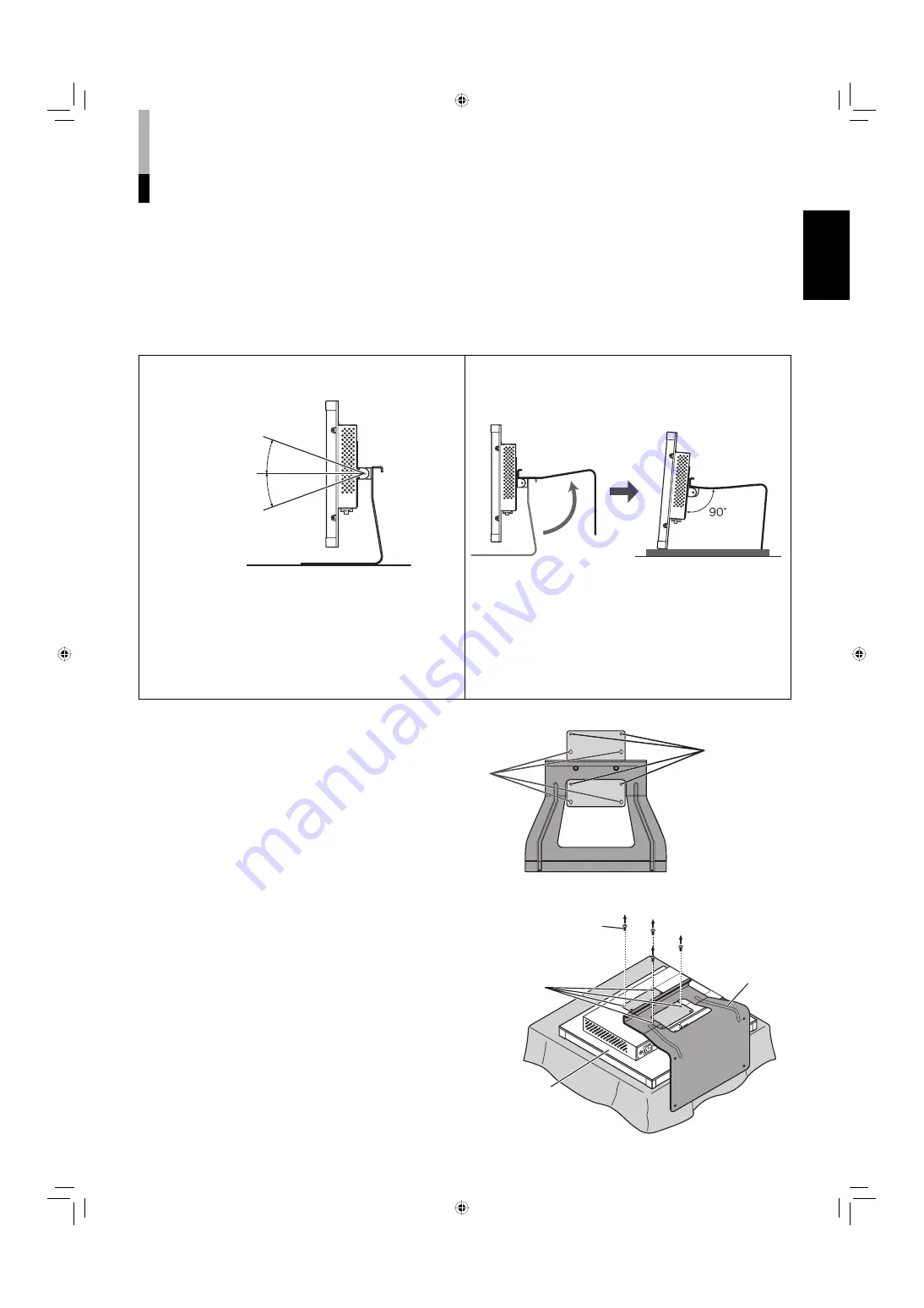
You can place the monitor in the following two ways when using the monitor on the supplied stand.

You can tilt the monitor upward or downward within 
the range of about 20° in each direction.

When the monitor is attached to the higher position of 
the stand (see below), you can lift the stand up by 90° 
and place the monitor as illustrated below.

NOTE:

•  Be careful not to pinch your fingers in the gap between the 

monitor and the stand.

•  Do not tilt the monitor upward more than 20°; otherwise 

the monitor may fall over.

•  When the monitor is attached to the lower position of the 

stand (see below), you cannot tilt the monitor downward.

NOTE:

•  Be careful not to pinch your fingers in the moving parts.
•  Make sure to lift the stand up until it stops; otherwise the 

monitor may fall over.

•  Place the monitor on a mat to avoid scratching the table 

surface.

•  Do not place the monitor in this way when the monitor is 

attached to the lower position of the stand.

To adjust the stand height

You can select the stand height—higher 
position or lower position.
•  For how to detach the stand, see below.

Screw holes 
for higher 
position

Screw holes 
for lower 
position

Stand

Monitor

VESA mounting holes

Screw (M4 x 10)

To detach the stand

NOTE:

•  Lay the monitor on a cloth with the LCD panel 

facing down to prevent the LCD panel being 
damaged.

about 20°

about 20°

LM170A&150A-EN.indb   11

LM170A&150A-EN.indb   11

07.11.2   3:21:24 PM

07.11.2   3:21:24 PM

Summary of Contents for LM-150A

Page 1: ...CCIONES MONITOR PANTALLA LCD DEUTSCH FRANÇAIS ITALIANO ESPAÑOL The illustration of the monitor is of LM 170A Die Abbildung des Monitors zeigt das Modell LM 170A Les illustrations du moniteur sont du LM 170A L illustrazione del monitor si riferisce al modello LM 170A La ilustración muestra el monitor LM 170A LM170A 150A COVER indd 3 LM170A 150A COVER indd 3 07 11 5 10 29 31 AM 07 11 5 10 29 31 AM ...

Page 2: ...éennes en vigueur concernant la compatibilité électromagnétique et à la sécurité électrique Représentant européen de la société Victor Company of Japan Limited JVC Technology Centre Europe GmbH Postfach 10 05 52 61145 Friedberg Allemagne Gentile Cliente Questa apparecchiatura è conforme alle direttive e alle norme europee relative alla compatibilità elettromagnetica e alla sicurezza elettrica Il r...

Page 3: ...INSTRUCTIONS LM 170A LM 150A LCD DISPLAY MONITOR ENGLISH The illustration of the monitor is of LM 170A LM170A 150A EN indb 1 LM170A 150A EN indb 1 07 11 2 3 21 16 PM 07 11 2 3 21 16 PM ...

Page 4: ...ty to operate the equipment NOTE This equipment has been tested and found to comply with the limits for a Class B digital device pursuant to Part 15 of the FCC Rules These limits are designed to provide reasonable protection against harmful interference in a residential installation This equipment generates uses and can radiate radio frequency energy and if not installed and used in accordance wit...

Page 5: ...supply of your home consult your product dealer or local power company Warning Do not use the same power cord for AC 120 V as for AC 220 240 V Doing so may cause malfunction electric shock or fire Note for United Kingdom power cord only The plug on United Kingdom power cord has a built in fuse When replacing the fuse be sure to use only a correctly rated approved type re fit the fuse cover Consult...

Page 6: ...emoving the power plug When the product is left unattended and unused for long periods of time unplug it from the wall outlet and disconnect the cables Do not overload wall outlets extension cords or convenience receptacles on other equipment as this can result in a risk of fire or electric shock Use only the accessory cord designed for this product to prevent shock Do not use the monitor for a lo...

Page 7: ...n to perform safety checks to determine that the product is in proper operating condition When connecting other products such as VCR s and personal computers you should turn off the power of this product for protection against electric shock Do not use attachments not recommended by the product manufacturer as they may be hazardous Do not install this product in the following places in a damp or d...

Page 8: ...ly valid in the European Union Safety Precautions cont Maintenance Unplug this product from the wall outlet before cleaning Screen To avoid irreparable change in appearance of the screen such as uneven color discoloration scratches be careful about the following Do not paste or stick anything with any glues or adhesive tapes Do not write anything on the screen Do not strike the screen with a hard ...

Page 9: ...stalling the monitor on the rack 12 How to Use the MAIN MENU 13 MAIN MENU items 13 How to Use the SET UP MENU 14 SET UP MENU items 15 How to Use the External Control 17 About the external control 17 How to use the MAKE TRIGGER terminal 17 Troubleshooting 18 Specifications 20 Dimensions 21 Available computer signals 22 7 ENGLISH LM170A 150A EN indb 7 LM170A 150A EN indb 7 07 11 2 3 21 22 PM 07 11 2...

Page 10: ...displayed adjust the volume level 00 to 50 by pushing the button left or right 6 MENU button Displays the MAIN MENU page 13 To display the SET UP MENU Press the CHROMA PHASE button 2 while pressing the MENU button page 14 7 SCAN SIZE button lamp Selects the screen size OVER 100 USER back to the beginning NOTE Memorized for each input For LM 170A when 100 is selected black bars appear on the top an...

Page 11: ...onitor is off the AC plug is not connected 7 About the status display When STATUS DISPLAY is set to ON page 16 the status information of the current input and the monitor settings is displayed for about 5 seconds in the following cases When you press the INPUT SELECT button of the current input When you change the inputs When the signal condition of the current input changes 1 Input status 2 Signa...

Page 12: ... video connection 3 REMOTE external control terminal MAKE TRIGGER Terminals for controlling the monitor by an external control Enables the monitor to be controlled by short circuiting the pin terminal in this terminal or by inputting the pulse signal How to Use the External Control on page 17 4 DVI D terminals e AUDIO terminal stereo mini jack Input terminal for the analog audio signals NOTE The b...

Page 13: ...e stand Do not tilt the monitor upward more than 20 otherwise the monitor may fall over When the monitor is attached to the lower position of the stand see below you cannot tilt the monitor downward NOTE Be careful not to pinch your fingers in the moving parts Make sure to lift the stand up until it stops otherwise the monitor may fall over Place the monitor on a mat to avoid scratching the table ...

Page 14: ...nting unit compliant with the VESA standard 100 mm x 100 mm NOTE Detach the stand first page 11 Ask your dealer to install 7 Installing the monitor on the rack Use a JVC s RACK MOUNT ADAPTER RK C157L1G not supplied NOTE Detach the stand first page 11 Ask your dealer to install LM170A 150A EN indb 12 LM170A 150A EN indb 12 07 11 2 3 21 25 PM 07 11 2 3 21 25 PM ...

Page 15: ... position of the picture automatically when analog RGB signals are input from the computer By using this function the picture is displayed as large as possible in the effective screen area Adjust the items in SIZE POSI ADJ RGB page 15 manually when you cannot get a good picture quality with AUTO ADJ all reset Restores all the settings and adjustments of the monitor to the factory settings Adjustme...

Page 16: ...ach operation 7 To exit the menu Select Next When video signals are input and SCAN SIZE is USER Ex When ASPECT is 4 3 When analog RGB signals are input from the computer 7 To go back to the previous screen Select Adjust Press CHROMA PHASE while pressing MENU Select reset Perform reset Select Adjust Select Adjust Select Adjust Select Adjust Next When selecting USER1 or USER2 in 2 Select Next Select...

Page 17: ... 00 40 SIZE POSI ADJ USER Adjusts the position and size of the picture This item is available only when video signals are input and SCAN SIZE page 8 is set to USER H SIZE 1 Adjusts the horizontal picture size 40 00 40 H POSI 1 Adjusts the horizontal picture position 40 00 40 V SIZE 4 3 1 Adjusts the vertical picture size for 4 3 aspect ratio 40 00 40 V SIZE 16 9 1 Adjusts the vertical picture size...

Page 18: ...ing messages except Control lock on do not appears CONTROL LOCK Turns on or off the control lock function to disable the buttons on the front panel Setting value ON OFF NOTE The following operations are available while this function is activated Turning on off the monitor Displaying the SET UP MENU by pressing CHROMA PHASE button while pressing the MENU button and turning CONTROL LOCK to OFF Opera...

Page 19: ...nges the input to DVI Invalid Valid 4 Changes the input to RGB Invalid Valid 5 6 Changes ASPECT to 16 9 Off On 7 External control Invalid Valid 2 8 GND 1 The TRIG trigger system switches each function by short circuiting for approx 1 second 2 External control the 7th pin terminal is controlled by the MAKE make contact system even when you select the TRIG trigger system Operation 1 Short circuit th...

Page 20: ...tly Select the correct input with the INPUT SELECT buttons 9 Is the power of the connected component on Is the signal being output from the connected component Turn on the power of the connected component and output video signals Or check if the video output of the component video output setting of the VCR or graphic board of the computer is set correctly No sound LM 170A only Is the signal cable ...

Page 21: ... enable control by the external control connected to the REMOTE terminal Disable the external control 17 Installing the driver is required when a computer is connected Use the driver of the graphic board installed into your computer the driver is supplied with the graphic board Or set the monitor to the standard display Recommended display setting 1280 x 1024 60 Hz LM 170A 1024 x 768 60 Hz LM 150A...

Page 22: ...ignal Format Video signal Composite video NTSC PAL B W 50 Hz 60 Hz Computer signal DVI D Available computer signals on page 22 Analog RGB Available computer signals on page 22 Audio Output Internal 1 W monaural Environmental Conditions Operating temperature 5 C 35 C 41 F 95 F Operating humidity 20 85 non condensing Power Requirements AC 100 240 V 50 Hz 60 Hz Rated Input Current 0 9 A 0 9 A Dimensi...

Page 23: ...the stand 342 13 1 2 291 11 1 2 70 5 2 7 8 28 5 1 1 8 70 5 2 7 8 28 5 1 1 8 334 13 1 4 373 6 14 3 4 338 6 13 3 8 330 6 13 1 8 295 6 11 3 4 at the higher position at the lower position at the higher position at the lower position 184 7 1 4 100 135 5 3 8 100 VESA mounting holes Size M4 depth 10 mm 280 11 1 8 280 11 1 8 184 7 1 4 LM170A 150A EN indb 21 LM170A 150A EN indb 21 07 11 2 3 21 30 PM 07 11 ...

Page 24: ...c 6 GND 14 Vertical sync 7 GND 15 DDC clock 8 GND External GND 7 Available computer signals The following computer signals can be displayed on the monitor Preset signals Signal name Screen resolution Vertical frequency reflesh rate For analog RGB signals In the following cases perform AUTO ADJ page 13 When inputting other signals than those listed in this table If the picture of the listed signals...

Page 25: ... 2007 Victor Company of Japan Limited 1007MKH MW TU LM170A 150A COVER indd 2 LM170A 150A COVER indd 2 07 11 5 10 29 31 AM 07 11 5 10 29 31 AM ...

Reviews: