background image

E34

4. Settings (continued)

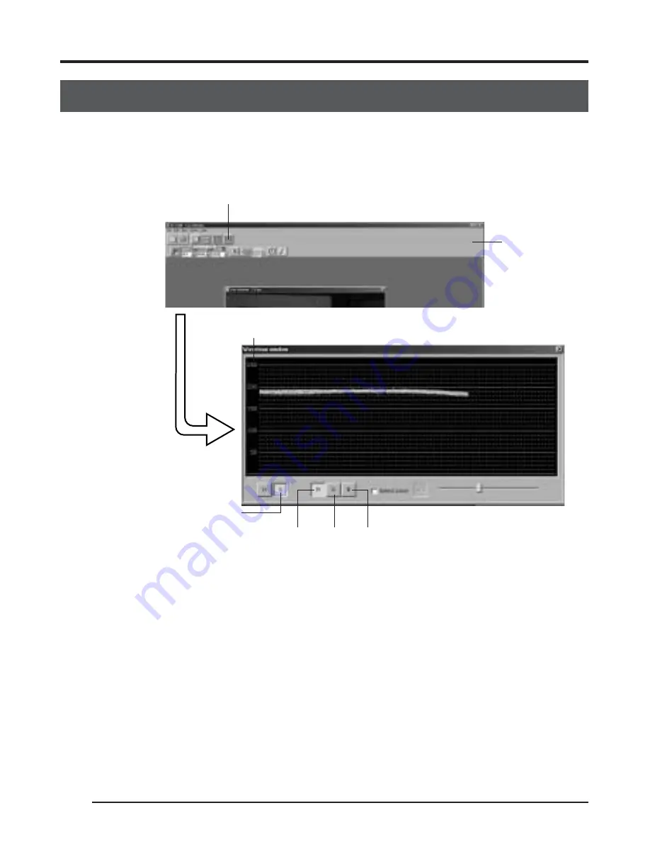
Adjustment of white shading

White shading can occur due to the combination of lenses and the optical system that 3CCD
cameras are equipped with.
If this happens, perform adjustment as described in the following.

1.

Shoot a white subject so that the entire screen is filled with white. (Illumination should be
uniform.)

2.

Adjust the white balance.

3.

Click the Waveform window button in the toolbar of the KY-LINK screen to display the set-
ting screen. Click the [V] and [R] button to display the waveform of the red channel in the
vertical direction.

4.

Adjust the shutter speed, etc. until the video signal level becomes about 170 – 190.

5.

On the white balance setting screen, set the Shading item to “ON”.

6.

Adjust Level (R) to make the gradient of the waveform as small as possible.

7.

Click the [G] button on the setting screen to switch to the waveform of the green channel.
Then adjust Level (G) to make the gradient of the waveform as small as possible.

8.

Click the [B] button on the setting screen to switch to the waveform of the blue channel.
Then adjust Level (B) to make the gradient of the waveform as small as possible.

9.

When adjustment of the white shading is completed, adjust the white balance.

Waveform window button

KY-LINK screen

tool bar

Video signal level

Setting screen

R button

G button B button

V button

Summary of Contents for KY-F75

Page 1: ...que KY F75 Illustration with optional lens attachment This instruction book is made from 100 recycled paper LWT0059 001B For Customer Use Enter below the Serial No which is located on the unit Retain this information for future reference Model No KY F75 Serial No Introduction Preparations Recording Settings Others ...

Page 2: ... should never be blocked by placing the appliance on a bed sofa rug or other similar surface This appliance should never be placed near or over a radiator or heat register This appliance should not be placed in a built in installation such as a bookcase unless proper ventilation is provided 9 This appliance should be operated only from the type of power source indicated on the marking label If you...

Page 3: ...perating instructions Adjust only those controls that are covered by the operating instructions as improper adjustment of other controls may result in damage and will often require extensive work by a qualified technician to restore the appliance to normal operation e If the appliance has been dropped or the cabinet has been damaged f When the appliance exhibits a distinct change in performance th...

Page 4: ...essional Europe Ltd Leiden Nederland JVC Plein De Heyderweg 2 2314 XZ Leiden Nederland tel 31 071 545 3333 III JVC Sales Office 8 JVC Professional Europe Ltd Stockholm Sweden Veddestavagen 15 S 175 62 Jarfalla Stockholm Sweden tel 46 08 7950400 9 JVC Professional Europe Ltd Tonsberg Norway PO Box 2012PT Wirgenes v5 Barkaker N 3103 Tonberg Norway tel 47 333 61600 10 JVC Professional Europe Ltd Tast...

Page 5: ...s type B equipment classified in accor dance with IEC Publication 601 1 Safety of medical elec trical equipment MEDICAL ELECTRICAL EQUIPMENT WITH RESPECT TO ELECTRICAL SHOCK FIRE MECHANICAL AND OTHER SPECIFIED HAZARDS ONLY IN ACCORDANCE WITH UL 2601 1 CAN CSA C22 2 NO 601 1 56PA AA P700MD AC Adaptor is designed to use in Hos pital or other Medical usage AA P700 AC Adaptor is designed to use for no...

Page 6: ...for USA This device complies with Part 15 of the FCC Rules Changes or modifications not approved by JVC could void the user s authority to operate the equipment INFORMATION FOR CANADA RENSEIGNEMENT POUR CANADA This Class B digital apparatus complies with Cana dian ICES 003 Cet appareil numérique de la classe B est conforme à la norme NMB 003 du Canada Changes or modifications not approved by JVC c...

Page 7: ...he sources of the disturbance KY F75 is designed and operated for non patient equipment when used in the hospi tal or other medical environments KY F75 and AA P700EG are tested and complied in accordance with IEC 601 1 safety standards The use of accessory equipment not complying with the equivalent safety require ments of this equipment may lead to reduce level of safety of the resulting system C...

Page 8: ...uction book CAUTION Cautionary notes concerning operation of the unit MEMO Reference such as restrictions of features etc Reference page or item In general the names of products manufactured by other companies and mentioned in these instructions are trademarks or registered trademarks of these companies Symbols like etc are not used in these instructions 4 Settings Opening and closing the Settings...

Page 9: ...lished by replacing the optical filter sepa rately sold Please consult the nearest JVC Service Center or your dealer with regards to replacement of the optical filter 1 Introduction Accessories and attachments INSTRUCTIONS Clamp filter 2 pcs For IEEE1394 cable and DC power cable page E14 E16 Wire clamp 5 pcs For clamping cables on the rear MEMO To allow control of the camera and allow the camera i...

Page 10: ...n this product is provided with at built in white spot compensa tion function page E38 Cautionary notes Influence of strong electric waves and magnets Screen noise and discolouration may occur when using the product near antennas of ra dios and televisions or near transformers monitors etc with strong magnetic force Comply with Regulatory FCC Port 15 Class B IEC60601 1 2 2001 EN55103 1 2 1996 Comp...

Page 11: ... bracket is mounted on the bottom of the camera when shipped the bracket can also be mounted on the top of the camera Mounting the camera page E18 쐋 Locking screws for the camera mounting bracket M2 6 6mm 3 units CAUTION Always use the attached screws Using screws that exceed 6mm may result in malfunction of the unit 쐏 Screw holes for mounting the camera 1 4 inch Used when mounting the camera to a...

Page 12: ...nt install the attached earth cable 1 Introduction continued IEEE1394 digital output con nector Digital output connector for video signal Used when connecting to the PC s IEEE 1394 host adapter Pin configurations of connectors page E8 LENS connector To connect the lens camera cable for iris control power supply Pin configurations of connectors page E9 Mounting and setting the lens page E15 LENS DC...

Page 13: ...AUTION Consult your JVC dealer concerning the re mote terminal connection Remote cable must use shielded cable Outer shield of remote cable must to connect 10 pin connector outer metal shell Do not input the external trigger during the first 10 seconds after the power is turned ON I O IN 3 3V CMOS Schmidt Trigger Pull up to 3 3V at 4 7k Ω OUT Open collector Conditions Contact point recommended Max...

Page 14: ...on the computer using the IEEE1394 cable Attach the clamp filter supplied with the camera to the IEEE1394 cable The power to the KY F75 can be supplied through the IEEE1394 connector of the computer Caution When the KY F75 is supplied with power though the IEEE1394 cable make sure that the capacity on the supplying side is sufficient to meet the consumption by the KY F75 approximately 600 mA in th...

Page 15: ...g the DC power cable Attach the clamp filter supplied with the KY F75 to the DC power cable Connect the camera cable from the lens to the LENS connector on the KY F75 Connect the zoom and focus control cable from the lens to the lens remote control The lens control possible with this unit is only control of the iris Control of zoom and focus requires a separately sold lens remote control unit 䡵 Pr...

Page 16: ...䡵 To transfer the camera s digital images to the computer the IEEE1394 PCI host adapter card and its driver must be installed in the computer Use the following IEEE1394 PCI host adapter card JVC KA FW4IU The driver is found on the CD ROM supplied with the KY F75 䡵 To display the camera image and control the camera the exclusive KY LINK appli cation software must be installed in the computer The KY...

Page 17: ...of the KY LINK application software as follows 햲 Insert the CD ROM supplied with the KY F75 into the computer s CD ROM drive 햳 Select the ENU Kylink folder on the CD ROM and double click Setup exe 햴 The setup screen appears Follow the instructions on the screen to execute the setup 햵 When the setup is completed the application software KY LINK will be ready to use after the computer has been resta...

Page 18: ...t be adhered to Precautions on power supply When supplying the KY F75 with power though the IEEE1394 cable make sure that the capacity on the supplying side is sufficient to meet the consumption by the KY F75 approximately 600 mA in the case of DC 12 V When supplying the KY F75 with power from the computer make sure that sufficient power is sup plied to the power supply connector of the IEEE1394 h...

Page 19: ...nector on the rear panel of the KY F75 Rotate the plug until it is securely locked Control of the iris is performed from the KY F75 4 When connecting to the lens remote control connect the plug female of the lens control cable to the remote control 5 Make settings on the setting screen of the application software KY LINK in accordance with the used lens 䡵 Iris mode settings on the Exposure and Len...

Page 20: ...attaching the filter clamp After inserting the plug completely tighten the se curing ring To reduce the emission of unwanted radio waves make sure to attach the provided clamp filter as shown in the figure on the left Wind the cable once around the clamp filter Attach the clamp filter as close as possible to the KY F75 as shown in the figure DC IN POWER DC IN DC IN Plug Ring Clamp filter VIDEO OUT...

Page 21: ...ng the power switch ON OFF in rapid succession may result in malfunctions such as failure to boot etc When power is supplied from the computer control of the motorized lens is not possible MEMO If power is supplied from both the IEEE1394 connector and from the DC IN connector the DC IN connector will have priority CAUTION In case of medical use 햲 Make sure to use Earth cable Refer the Ilustration ...

Page 22: ...ing the camera mounting bracket position Mounting method Rotation prevention hole Camera mounting screw hole Camera mounting bracket When shipped the camera mounting bracket is mounted on the bottom of the unit To mount it on the top of the unit simply remove the 3 locking screws holding the camera mounting bracket CAUTION Always use the attached screws Using screws that exceed 6mm may result in m...

Page 23: ...of the unit may result in bodily injury To prevent the unit from falling connect the unit to a strong surface with a wire chain etc When connecting such chain use the bracket locking screw hole on the side which the camera mounting bracket is not mounted M2 6 6mm Take special caution to the length of the optional wire as well For the fall preventive wire use the one with the strength that is more ...

Page 24: ...to the KY F75 the camera image can be frozen by the external trigger input signal Basic operations for recording 1 Turn ON the KY F75 Wait for 5 seconds or more 2 Start the KY LINK application software 䡵 Make camera settings as required Menu screen settings 墌 page E24 䡵 Freeze the image as required Still image 3 Capture the still image on the computer Capture 4 Save the captured image on the compu...

Page 25: ...INK 씮 KY LINK The KY LINK start screen appears KY LINK start screen 2 Select Camera and then click the OK button The selected camera image is displayed Live image is shown at a rate of 7 5 frames per second MEMO For details on the operation of the KY LINK application software see the Help file for the KY LINK application software This manual only explains the broad outlines of the operation ...

Page 26: ...he flash When a flash is connected to the REMOTE connector on the KY F75 the flash can be made to fire in synch with KY LINK freeze operation or the external trigger input 墌 page E43 However in the following case the flash will fire irrespective of the trigger During auto white balance operation When one or more of the functions auto iris EEI and ALC is are used MEMO The freeze function of the KY ...

Page 27: ...the Save As button and then give the image a name and save the file Closing the KY LINK application 䡵 Select Exit from the File menu Caution Wait for 5 seconds or more after closing the KY LINK before turning the KY F75 OFF Do not turn OFF the power to the camera while the KY LINK is running Capture button Single Capture Multi Capture Timer Capture Set Reset Trigger Capture Set Reset Save As butto...

Page 28: ...ab The Settings screen consists of 6 different cat egories of setting screens Exposure Used for image level related set tings such as Iris Shutter Gain etc White balance Used for settings of color tem perature white balance etc Process Used for image quality related set tings such as detail compensation gamma white spot compensation etc Color matrix Used for settings related to color tone Lens Use...

Page 29: ...he Settings screen Click the X Close button Saving the setting values on the computer Save the setting values as a file on the computer by selecting File 씮 Save Read out the setting values saved on the computer by selecting File 씮 Load To return the setting values to the factory defaults read in DefaultF75 dat Close button File Load Save ...

Page 30: ...d is 2 sec or slower in the V SCAN mode Iris settings Gain settings EEI limit setting Sets the slowest shutter speed when the shutter mode is EEI ALC max settings Sets the maximum ALC sensitivity Level settings Set the level by sliding the slider bar with the mouse Also fine adjustment can be made with the keyboard s 씯 and 씮 keys For selecting the set ting value Select the setting value from the p...

Page 31: ...ion area for the image level when Auto Iris ALC or EEI is used When selected the detection area is shown on the screen Selects the detection method of the detection area when Auto Iris ALC or EEI is used NORMAL normal positon PEAK detects the peak brightness level for better view of highly bright objects AVG detects the avarage brighhtness for better view of objects Item Iris mode Set Value AUTO M...

Page 32: ...ut Item Shutter 4 Menu screen settings continued Set Value STEP V SCAN EEI OFF RANDOM 4s 2s 1s 1 2s 1 4s 1 8s 1 15s 1 30s 1 60s 1 125s 1 250s 1 500s 1 1000s 1 2000s 4 010s 1 7 501s 1 5906 836s 1 7 501s 1 124 176s 1 5648 194s MEMO When the shutter speed is slower than 1 7 5 s the follow ing phenomena may occur Time will be required for the auto white auto iris and ALC operations If the shutter spee...

Page 33: ...he Level item Sets the maximum sensitivity of ALC which automatically switches the sensitivity in accordance with ambient bright ness Sets the minimum value for the shutter speed when the shutter mode is set to EEI 1 7 5s Set to 1 7 5s 1s Set to 1s Item Gain Level When STEP is selected Level When V GAIN is selected ALC max EEI limit Set Value STEP ALC V GAIN 0dB 6dB 12dB 0 0dB 0 2dB 0 4dB 12dB 12d...

Page 34: ...this adjustment after white balance is completed 䡵 If white shading adjustment is performed perform white balance adjustment again Auto white button Click this button when auto white balance adjustment should be performed Sets the standard color temperature for the white balance adjustment White balance adjustment As the color of the light color temperature dif fers with the light source the white...

Page 35: ...SET The white balance is fixed at the setting made for the Color temp item The red color in the white balance can be adjusted when White bal is set to AUTO or MANUAL Increasing the value Red tint of screen becomes stronger Decreasing the value Red tint of screen becomes weaker The blue color in the white balance can be adjusted when White bal is set to AUTO or MANUAL Increasing the value Blue tint...

Page 36: ...of the screen and deeper red at the bottom The color green of the white shading is adjusted only when Shading is set to ON Increase the number paler green at the bottom of the screen and deeper green at the top Decrease the number paler green at the top of the screen and deeper green at the bottom The color blue of the white shading is adjusted only when Shading is set to ON Increase the number pa...

Page 37: ...djustment may take a while 䡵 In accordance with the results of the auto white balance fine adjustment can be performed using the Level R B slider bars MEMO When the colour temperature of the subject changes as the darkness increases do not change the illumination Instead narrow the lens iris and take the white balance again by pressing the Auto White button When the shutter speed is set to 2 sec o...

Page 38: ...ction 4 Adjust the shutter speed etc until the video signal level becomes about 170 190 5 On the white balance setting screen set the Shading item to ON 6 Adjust Level R to make the gradient of the waveform as small as possible 7 Click the G button on the setting screen to switch to the waveform of the green channel Then adjust Level G to make the gradient of the waveform as small as possible 8 Cl...

Page 39: ...nal level before GAMMA compensation Contents Used to set whether to emphasize details ON changes the detail emphasis OFF no detail emphasis The emphasis level of the detail is adjusted when Dedail is set to ON increase the number Sharpen the detail decease the number Soften the detail Adjusted when you want to reduce noise in black areas Noise in black areas is reduced because the frequency charac...

Page 40: ...number Improves the gradation of black areas However the gradation of bright areas becomes poorer Selects whether the camera image should be negative signal ON Conversion to negative signal is made OFF Conversion to negative signal is not made Selects whether DSP Digital Signal Processing should be bypassed NORMAL Not bypassed BYPASS Bypassed In this case the following setting items are fixed as i...

Page 41: ...aker Makes the compensation value larger Decreasing the value Blue tint becomes stronger Makes the compensation value smaller Used to set whether to use automatic adjustment of the black level in accordance with the signal level during shooting Use this adjustment when the black level of the video image fluctuates Black level is adjusted Increasing the value Lowers the black level Makes the compen...

Page 42: ...hite spot compensation function cannot compensate completely for all white spots White spot detection and compensation by this camera can be performed under the following condi tions White spot compensation is not possible under other conditions Even when these conditions are met the properties of the white spots may prevent compensation Detection and compensation area Area of 1024 1024 pixels at ...

Page 43: ... set the color tone of the camera image Selects the color matrix Slider bar Valid when ON is selected as the Color matrix Make adjustments by dragging the slider bars with the mouse Fine adjustment can be made with the keyboard s 씯 and 씮 keys ...

Page 44: ... Used to adjust the R G signal 0 25 Used to adjust the R B signal 0 25 Used to adjust the G R signal 0 25 Used to adjust the G R signal 0 25 Used to adjust the G B signal 0 25 Used to adjust the G B signal 0 25 Used to adjust the B R signal 0 25 Used to adjust the B G signal 0 25 Used to adjust the B G signal 0 25 Set Value ON OFF 0 1 31 Item Color matrix R G R G G R G R G B G B B R B G B G Color ...

Page 45: ...ted When using manual iris while motorized lens is mounted When the motorized lens cable is not connected to the LENS connector the setting automatically becomes MANUAL Used to set the iris level when the Iris mode is set to MANUAL When an motorized lens is used this sets the iris level when manual iris control on the camera is used Increasing the value Opens the iris Decreasing the value Closes t...

Page 46: ...on are made invalid Contents Sets the method for canceling the FREEZE when the monitor screen is in FREEZE condition MANUAL Cancelled by trigger input AUTO1s Cancelled after 1 second AUTO3s Cancelled after 3 seconds AUTO5s Cancelled after 5 seconds OFF Not cancelled When set to AUTO or OFF the displayed screen can be updated by trigger input during the FREEZE condition Selects whether or not a col...

Page 47: ...nt that the FLASH signal is outputted is output as the next frame In the case of video output output stops with shooting of this frame and the image on the PC s monitor will be in the FREEZE condition How to cancel the FREEZE condition can be selected page E42 Freeze cancel item The trigger interval must be minimum 3 frames 405 msec at a shutter speed of 1 7 5 s or faster When the FREEZE cancel mo...

Page 48: ...the CCD regardless of the trigger When Shutter on the EXPOSURE screen is set to EEI When Gain on the EXPOSURE screen is set to ALC When Iris mode on the EXPOSURE screen is set to AUTO While AW Auto White is operating MEMO In the condition where the shutter mode is RANDOM the image quality may deteriorate at the time of FREEZE as noise may be applied or white spots may appear 1 15s 1 8s 1 60s 1 30s...

Page 49: ...ther words the signal level is adjusted in the range of 2 graduations of the aperture under dark lighting and 8 graduations under bright lighting When the IRIS mode is set to manual the sensitivity and electronic shutter change continuously while the iris setting stays fixed page E27 Iris mode This feature holds the advantage of being able to shoot under changing light conditions without the depth...

Page 50: ...DC 12V when AA P700 is used DC8V to 40V IEEE1394 power supply Power consumption 12 W when AA P700 is used including lens 7 2 W when IEEE1394 power supply 12V without lens Mass 750g Connectable PC models Pentium III 1 GHz or higher DOS V PC AT compatible machine Pentium 4 1 3 GHz or higher is recom mended Memory 64 MB or more 20 MB or more empty hard disk space space for application software instal...

Page 51: ...E47 External dimensions unit mm C Mount 1 4 inch screw DIGITAL CAMERA KY F75U C MOUNT 41 5 14 1 142 5 150 88 70 80 Design and specifications are subject to change without notice ...

Page 52: ...WT0059 001B KY F75 3CCD Digital Camera is a registered trademark owned by Victor Company Of Japan Limited is a registered trademark in Japan the U S A the U K and many other countries 2004 Victor Company Of Japan Limited ...

Page 53: ...3CCD Digitale Kamera KY F75 BEDIENUNGSANLEITUNG Einleitung Vorbereitungen Aufnahme Einstellungen Sonstiges ...

Page 54: ...den ACHTUNG Verwenden Sie zurVermeidung von elektrischem Schlag und Feuer keine andere Stromversorgung Änderungen der in dieser Bedienungsanleitung g e g e b e n e n D a t e n a u f G r u n d v o n Entwurfsänderungen bleiben jederzeit vorbehalten ACHTUNG Öffnen Sie das Gehäuse nicht um die Gefahr von elektrischem Schlag zu vermeiden Im Inneren sind keine Teile die durch den Benutzer gewartet werde...

Page 55: ...t halten Bei Verwendung in Krankenhäusern oder anderen medizinischen Umgebungen darf die Digitalkamera KY F75 nur zusammen mit Geräten betrieben werden die nicht am Patienten eingesetzt werden Die Digitalkamera KY F75 und der Netzadapter AA P700EG wurden getestet und enstprechen den Sicherheitsstandards nach IEC 601 1 DieVerwendung von Zubehör das nicht den Sicherheitsanforderungen dieses Gerätes ...

Page 56: ... 26 Einstellungsbildschirm für Weißabgleich 30 Durchführen von automatischem Weißabgleich 33 Einstellung der Weißschattierung 34 Bildschirm für Prozesseinstellungen 35 Ausgleich von weißen Punkten 38 Bildschirm für Farbmatrixeinstellungen 39 Bildschirm für Objektiveinstellungen 41 Bildschirm für Systemeinstellungen 42 5 Sonstiges Synchronisation von Blitz und Auslöser 43 Hinweise zu ALC und EEI Be...

Page 57: ...uft ist Aufnahme im nahen Infrarotbereich möglich Bitte wenden Sie sich für das Auswechseln des optischen Filters an Ihr nächstes JVC Wartungszentrum oder an Ihren Händler 1 Einleitung Zubehör und Zusatzgeräte Bedienungsanleitung Klemmfilter 2 Stück Für IEEE1394 Kabel und Gleichstrom Stromversorgungskabel Seite G14 G16 Kabelklammer 5 Stück Zum Festklemmen von Kabeln an der Rückseite MEMO Um Steuer...

Page 58: ...formatoren Monitoren usw mit einem starken Magnetfeld kann es auf dem Bildschirm zu Störungen und Verfärbung kommen Konformität mit folgenden Bestimmungen FCC Teil 15 Klasse B IEC60601 1 2 2001 EN55103 1 2 1996 Kompatible Objektive Seite G15 Anbringen und Einstellen des Objektivs Obwohl die Objektivfassung dieses Erzeugnisses eine typische C Fassung ist ist zu beachten daß es Begrenzungen für die ...

Page 59: ... angebracht kann aber auch auf der Oberseite der Kamera angebracht werden Anbringen der Kamera Seite G18 쐋 S t e l l s c h r a u b e n f ü r d i e Kamerahalterung M2 6 6 mm 3 Stück ACHTUNG Unbedingt die mitgelieferten Schrauben verwenden Verwendung von Schrauben mit einer Länge von mehr als 6 mm kann Fehlfunktion des Gerätes verursachen 쐏 Gewindelöcher für Anbringen der Kamera 1 4 Zoll Für Anbring...

Page 60: ...gerätes Seite G16 쐅 Funktionsfähiges Erdungskabel Schließen Sie zur Verwendung der Kamera als Teil eines medizinischen Gerätes das beiliegende Erdungskabel an 1 Einleitung fortgesetzt Digitaler Ausgangsanschluss IEEE1394 Digitalausgangsanschluss für Videosignal Verwendet zum Anschluss an den IEEE1394 Hostadapter des Computers Stiftbelegung der Anschlüsse Seite G8 Anschluss LENS Objektiv Zum Anschl...

Page 61: ...d der ersten 10 Sekunden nach dem Einschalten der Stromversorgung ein Ein Ausgang IN 3 3V CMOS Schmidt Trigger Anheben zu 3 3V durch 4 7k Ω OUT Offener Kollektor ACHTUNG Verwenden Sie ein Gerät mit einem maximalen Stromverbrauch von 400 mA oder weniger 1 4 3 6 7 8 5 2 1 2 8 7 10 6 3 4 5 9 4 3 2 8 9 1 7 6 11 5 10 12 Kompatibler Stecker HF 10A 10P 10P Hirose Electronics Stift Nr Signalname 1 2 TRG I...

Page 62: ...94 Hostadapter am Computer an Bringen Sie den mit der Kamera mitgelieferten Klemmfilter am IEEE1394 Kabel an Die Stromversorgung für die KY F75 kann über den IEEE1394 Anschluss des Computers erfolgen Achtung Wenn die KY F75 über das IEEE1394 Kabel mit Strom versorgt wird so stellen Sie sicher dass die Kapazität auf der Versorgungsseite ausreichend ist um dem Stromverbrauch der KY F75 zu entspreche...

Page 63: ... mitgelieferten Klemmfilter am Gleichstrom Stromversorgungskabel an Schließen Sie das Kamerakabel vom Objektiv an den Anschluss LENS an der KY F75 an Schließen Sie das Kabel für Zoom und Scharfeinstellung vom Objektiv an die Objektivfernbedienung an Die mit diesem Gerät mögliche Steuerung des Objektivs ist nur Blendenregelung Regelung von Zoom und Scharfeinstellung erfordert eine separat erhältlic...

Page 64: ... der Digitalbilder von der Kamera zum Computer muss die IEEE1394 Hostadapter Karte im Computer installiert werden und ihr Treiber muss im Computer installiert werden Verwenden Sie die folgende IEEE1394 Hostadapter Karte JVC KA FW41U Der Treiber ist auf der mit der KY F75 mitgelieferten CD ROM zu finden 䡵 Für Anzeige des Kamerabildes und Bedienung der Kamera muss die exklusive Anwendungssoftware KY...

Page 65: ...ROM 2 Installieren Sie die Anwendungssoftware KY LINK wie folgt 햲 Legen Sie die mit der KY F75 mitgelieferte CD ROM in das CD ROM Laufwerk des Com puters ein 햳 Wählen Sie den Ordner ENU Kylink auf der CD ROM und doppelklicken Sie Setup exe 햴 Der Installierungsbildschirm erscheint Befolgen Sie die Anweisungen auf dem Bildschirm für die Installation 햵 Nach beendigter Installation kann die Anwendungs...

Page 66: ...nweise für die Stromversorgung Wenn die KY F75 über das IEEE1394 Kabel mit Strom versorgt wird so stellen Sie sicher dass die Kapazität auf der Versorgungsseite ausreichend ist um dem Stromverbrauch der KY F75 zu entsprechen etwa 600 mA bei 12 V Gleichstrom Wenn die KY F75 vom Computer her mit Strom versorgt wird so stellen Sie sicher dass der Stromversorgungsanschluss der IEEE1394 Hostadapter Kar...

Page 67: ...e der KY F75 an Drehen Sie den Stecker bis er sicher verriegelt ist Die Blende wird von der KY F75 her gesteuert 4 Schließen Sie zum Anschluss an die Objektivfernbedienung die Steckbuchse des Objektivbedienungskabels an die Fernbedienung an 5 Machen Sie die Einstellungen am Einstellungsbildschirm der Anwendungssoftware KY LINK entsprechend dem verwendeten Objektiv 䡵 Blendenmoduseinstellungen an de...

Page 68: ...ektivs usw sollte das Gleichstrom Stromversorgungskabel am Anschluss DC IN der KY F75 und am Anschluss TO CAMERA des Netzgerätes AA P700 angeschlossen werden ACHTUNG Achten Sie darauf das Netzgerät AA P700 zu verwenden Stellen Sie sicher dass der Hauptschalter des Netzgerätes ausgeschaltet ist OFF bevor angeschlossen wird Anschluss bei eingeschalteter Stromversorgung kann die KY F75 beschädigen 䡵 ...

Page 69: ...ersorgung wieder einschalten Schnelles Ein und Ausschalten der Stromversorgung kann Fehlfunktionen wie Startversagen usw verursachen Bei Stromversorgung vom Computer her ist Bedienung des motorisierten Objektivs nicht möglich MEMO Bei Stromversorgung über den IEEE1394 Anschluss und den Anschluss DC IN hat der Anschluss DC IN Vorrang ACHTUNG Bei medizinischer Verwendung 햲 Verwenden Sie ein Erdungsk...

Page 70: ...en der Kamerahalterung Anbringungsmethode Loch zur Verhütung von Verdrehen Stativgewinde Kamerahalterung Beim Versand ist die Kamerahalterung an der Unterseite des Gerätes angebracht Entfernen Sie einfach die drei Halteschrauben der Kamerahalterung wenn die Kamerahalterung an der Oberseite des Gerätes angebracht werden soll ACHTUNG Unbedingt die mitgelieferten Schrauben verwenden Verwendung von Sc...

Page 71: ...s Gerätes kann Körperverletzungen verursachen Verbinden Sie das Gerät zum Verhüten von Herunterfallen mit einem Drahtseil usw mit einer festen Oberfläche Verwenden Sie zum Anschließen eines solchen Drahtseils eins der Halterungsschraubenlöcher auf der Seite auf der die Halterung nicht angebracht ist M2 6 6 mm Auch besonders auf die Länge der optionalen Drähte achten Verwenden Sie für den Fallschut...

Page 72: ...des externen Auslösersignals ein Standbild erhalten werden Grundbetrieb für die Aufnahme 1 Schalten Sie die KY F75 ein ON Warten Sie mindestens 5 Sekunden 2 Starten Sie die Anwendungssoftware KY LINK 䡵 Machen Sie die erforderlichen Kameraeinstellungen Einstellungen am Menübildschirm 墌 Seite G24 䡵 Erhalten Sie ein Standbild wie erforderlich Einzelbild 3 Erfassen Sie das Standbild auf dem Computer E...

Page 73: ...INK 씮 KY LINK Der KY LINK Startbildschirm erscheint KY LINK Startbildschirm 2 Wählen Sie die Kamera und klicken Sie OK Das gewählte Kamerabild wird angezeigt Das Live Bild wird mit einer Rate von 7 5 Halbbildern pro Sekunde angezeigt MEMO Beziehen Sie sich für Einzelheit zur Anwendungssoftware KY LINK auf die Hilfe Datei für die Anwendungssoftware KY LINK Diese Anleitung erklärt den Betrieb nur im...

Page 74: ...den Verriegelung mit dem Blitz Wenn ein Blitz am Anschluss REMOTE an der KY F75 angeschlossen ist kann der Blitz synchron mit dem Standbildbetrieb von KY LINK oder dem externen Auslöseeingang ausgelöst werden 墌 Seite G43 In den folgenden Fällen wird der Blitz jedoch unabhängig vom Auslöser ausgelöst Während automatischem Weißabgleich Wenn mindestens eine der Funktionen Autoblende EEI und ALC verwe...

Page 75: ...ken Sie die Save As taste geben Sie dem Bild einen Namen und speichern Sie die Datei Schließen der Anwendungssoftware KY LINK 䡵 Wählen Sie Exit im Dateimenü Achtung Warten Sie nach dem Schließen von KY LINK mindestens 5 Sekunden bevor Sie die KY F75 ausschalten Schalten Sie die Stromversorgung zur Kamera nicht aus während KY LINK läuft Save As File Exit Single Capture Multi Capture Timer Capture S...

Page 76: ...ildschirm besteht aus sechs v e r s c h i e d e n e n K a t e g o r i e n v o n Einstellungsbildschirmen Exposure Für mit dem Bildpegel zusammenhängende Einstellungen wie Blende Verschluss Verstärkung usw White balance Für Einstellungen für Farbtemperatur Weißabgleich usw 4 Wahl des Einstellungsbildschirms Klicken Sie auf dem der einzustellenden Kategorie entsprechenden Wahlreiter Der gewählte Ein...

Page 77: ...llungsbildschirm Klicken Sie die Taste X Schließen Speichern der Einstellwerte auf dem Computer Speichern Sie die Einstellwerte als eine Datei auf dem Computer indem Sie File Datei 씮 Save Speichern wählen Lesen Sie die auf dem Computer gespeicherten Daten aus indem Sie File Datei 씮 Load wählen Lesen Sie für Rückstellung der Einstellwerte zu den Werkseinstellungen DefaultF75 dat ein Schließtaste Fi...

Page 78: ...2 sec oder langsamer ist Blenden einstellungen Verstärkungseinstellungen EEI Grenzwerteinstellung Einstellung der langsamsten Verschlusszeit wenn der Verschlussmodus EEI ist Maximale ALC Einstellung Einstellung der maximalen ALC Empfindlichkeit Pegeleinstellungen Stellen Sie den Pegel durch Verschieben des Schiebereglers mit der Maus ein Feineinstellung kann mit dem Tasten 씯 und 씮 der Tastatur gem...

Page 79: ...hes für den Bildpegel beiVerwendung von automatischer Blende ALC oder EEI Wenn gewählt wird der Entdeckungsbereich auf dem Bildschirm angezeigt Wahl der Entdeckungsmethode für den Entdeckungsbereich wenn automatische Blende ALC oder EEI verwendet wird NORMAL Normale Position PEAK Entdeckung des Spitzenwertes für den Helligkeitspegel für bessere Darstellung sehr heller Objekte AVG Entdeckung der du...

Page 80: ...lung an Speed wenn STEP gewählt ist Speed wenn V SCAN gewählt ist Speed wenn RANDOM gewählt ist Restart Einstellwert STEP V SCAN EEI OFF RANDOM 4s 2s 1s 1 2s 1 4s 1 8s 1 15s 1 30s 1 60s 1 125s 1 250s 1 500s 1 1000s 1 2000s 4 010s 1 7 501s 1 5906 836s 1 7 501s 1 124 176s 1 5648 194s MEMO Wenn die Verschlusszeit langsamer als 1 7 5 sec ist kann es zu den folgenden Erscheinungen kommen Für automatisc...

Page 81: ...em Punkt Level Pegel geändert werden Stellt die maximale Empfindlichkeit für ALC ein wodurch die Empfindlichkeit automatisch entsprechend der Umgebungshelligkeit umgeschaltet wird Stellt den Mindestwert für die Verschlusszeit ein wenn der Verschlussmodus auf EEI eingestellt ist 1 7 5s Auf 1 7 5 s eingestellt 1s Auf 1 s eingestellt Punkt Gain Level wenn STEP gewählt ist Level wenn V GAIN gewählt is...

Page 82: ...annt 䡵 Führen Sie diese Einstellung nach dem Weißabgleich durch 䡵 Wenn Einstellung der Weißschattierung durchgeführt worden ist so führen Sie erneut Weißabgleich durch Taste für automatischen Weißabgleich Klicken Sie diese Taste wenn automatischer Weißabgleich durchgeführt werden soll Einstellen der Standardfarbtemperatur für die Einstellung des Weißabgleichs Weißabgleicheinstellung Da sich die Li...

Page 83: ...t Level R Roter Pegel und Level B Blauer Pegel erreicht werden MANUAL Der Weißabgleich kann mit Level R Roter Pegel und Level B Blauer Pegel geändert werden PRESET Der Weißabgleich ist auf die am Punkt Color temp Farbtemperatur gemachte Einstellung fixiert Die rote Farbe im Weißabgleich kann eingestellt werden wenn White bal Weißabgleich auf AUTO Automatisch oder MANUAL Manuell gestellt ist Erhöhe...

Page 84: ...schirms und stärkeres Rot am Unterteil Die grüne Farbe wird bei der Weißwert Korrektur nur eingestellt wenn Shading auf ON gestellt ist Ein höherer Wert Schwächeres Grün am Unterteil des Bildschirms und stärkeres Grün am Oberteil Ein kleinerer Wert Schwächeres Grün am Oberteil des Bildschirms und stärkeres Grün am Unterteil Die blaue Farbe wird bei der Weißwert Korrektur nur eingestellt wenn Shadi...

Page 85: ...m Ergebnis des automatischen Weißabgleichs kann Feineinstellung mit den Gleitschiebern Level R B Pegel R B durchgeführt werden MEMO Wenn sich die Farbtemperatur des Objektes mit zunehmender Dunkelheit ändert so ändern Sie nicht die Beleuchtung Stellen Sie deshalb die Objektivblende auf eine geringere Öffnung ein und führen Sie erneut Weißabgleich durch Drücken der Taste Auto White durch Wenn eine ...

Page 86: ...en Sie die Verschlusszeit usw ein bis der Videosignalpegel etwa 170 bis 190 ist 5 Stellen Sie den Punkt Shading Schattierung am Einstellungsbildschirm für den Weißabgleich auf ON Ein 6 Stellen Sie den Pegel R so ein dass die Steigung der Wellenform so klein wie möglich wird 7 Klicken Sie die Taste G am Einstellungsbildschirm um zur Wellenform für den grünen Kanal umzuschalten Stellen Sie den Pegel...

Page 87: ...Betonung der Einzelheiten OFF Keine Betonung der Einzelheiten Der Betonungspegel für Einzelheiten wird eingestellt wenn Detail auf ON gestellt wird Den Wert erhöhen Schärfere Einzelheiten Den Wert verringern Weichere Einzelheiten Einstellung erfolgt zur Verringerung von Bildrauschen in schwarzen Bereichen Das Bildrauschen in schwarzen Bereichen wird verringert da die Frequenzcharakteristiken von B...

Page 88: ...passt ist NORMAL D i e G a m m a k u r ve ve r w e n d e t d e n Standardwert 0 45 ADJUST Für Änderung der Gammakurve einstellen Die Gammakurve kann nur eingestellt werden wenn Gamma auf ADJUST gestellt ist Erhöhen des Wertes Die Gradation der hellen Bereiche wird verbessert aber die Gradation von dunklen Bereichen wird schlechter Verringern des Wertes Die Gradation der schwarzen Bereiche wird ver...

Page 89: ...wird schwächer Die Kompensation wird größer Verringern des Wertes Die bläuliche Tönung wird stärker Die Kompensation wird kleiner Verwendet zum Einstellen ob automatische Einstellung des Schwarzpegels entsprechend dem Signalpegel während der Aufnahme verwendet werden soll oder nicht Verwenden Sie diese Einstellung wenn der Schwarzpegel des Videobildes schwankt Der Schwarzpegel wird eingestellt Erh...

Page 90: ...nicht alle weißen Punkte vollkommen ausgleichen Entdeckung und Ausgleich von weißen Punkten durch diese Kamera muß unter den folgenden Bedingungen durchgeführt werden Unter anderen Bedingungen ist Ausgleich von weißen Punkten nicht möglich Selbst wenn diese Bedingungen erfüllt werden können die Eigenschaften der weißen Punkte den Ausgleich verhüten Entdeckungs und Ausgleichsbereich Ein Bereich von...

Page 91: ...s Farbtons für das Kamerabild Wahl der Farbmatrix Gleitschieber Nur wirksam wenn ON für die Farbmatrix gewählt ist Stellen Sie den Pegel durch Verschieben des Gleitschiebers mit der Maus ein Feineinstellung kann mit den Tasten 씯 und 씮 der Tastatur gemacht werden ...

Page 92: ... des R G Signals 0 bis 25 Zum Einstellen des R B Signals 0 bis 25 Zum Einstellen des G R Signals 0 bis 25 Zum Einstellen des G R Signals 0 bis 25 Zum Einstellen des G B Signals 0 bis 25 Zum Einstellen des G B Signals 0 bis 25 Zum Einstellen des B R Signals 0 bis 25 Zum Einstellen des B G Signals 0 bis 25 Zum Einstellen des B G Signals 0 bis 25 Einstellwert ON OFF 0 1 31 Punkt Color matrix R G R B ...

Page 93: ...ebracht ist Bei Verwendung von manuelles Blende mit einem motorisierten Objektiv Wenn das Kabel des motorisierten Objektivs nicht angeschlossen ist wird die Einstellung automatisch zu MANUAL Zum Einstellen des Blendenpegels wenn der Blendenmodus auf MANUAL gestellt ist Wenn ein motorisiertes Objektiv verwendet wird stellt dies den Blendenpegel ein wenn manuelle Blendenregelung an der Kamera verwen...

Page 94: ...andbild FREEZE ein wenn der Monitorbildschirm im Standbildzustand FREEZE ist und der Anschluss über den Digitalausgang hergestellt ist MANUAL Annullieren durch Auslösereingang AUTO1s Annullieren nach 1 Sekunde AUTO3s Annullieren nach 3 Sekunden AUTO5s Annullieren nach 5 Sekunden OFF Nicht annulliert Bei Einstellung auf AUTO Automatisch oder OFF Aus kann der angezeigte Bildschirm während des Standb...

Page 95: ...ufgenommene Bild wird als das nächste Bild ausgegeben Im Fall von Videoausgang hält der Ausgang mit der Aufnahme dieses Halbbildes an und das Bild auf dem Monitor des Personalcomputers wird ein Standbild Die Methode zum Annullieren des Standbildzustands FREEZE kann gewählt werden Seite G42 Punkt Freeze cancel Das Auslöserintervall muss bei einer Verschlusszeit von 1 7 5 s oder länger mindestens 3 ...

Page 96: ...hen oder Auftreten von weißen Punkten kommen kann In den folgenden Situationen wird das Blitzsignal FLASH kontinuierlich synchron mit dem CCD Element erzeugt unabhängig vom Auslöser Wenn Shutter Verschluss am Bildschirm EXPOSURE Belichtung auf EEI gestellt ist Wenn Gain Blendenmodus am Bildschirm EXPOSURE Belichtung auf ALC Automatik gestellt ist Wenn Iris mode Blendenmodus am Bildschirm EXPOSURE ...

Page 97: ...lpegel erhalten werden Der ALC Modus erhöht die Empfindlichkeit von 0 dB zu 12 dB unter schwacher Beleuchtung und der EEI Modus stellt unter der richtigen Beleuchtung automatisch den Bereich von 1 7 5 s bis 1 2384 7 s berechneter Wert ein In anderen Worten wird der Signalpegel unter schwacher Beleuchtung im Bereich von zwei Blendenstufen und unter heller Beleuchtung im Bereich von acht Blendenstuf...

Page 98: ...s 40 V IEEE1394 Stromversorgung Stromverbrauch 12 W bei Verwendung von AA P700 einschließlich Objektiv 7 2 W mit IEEE1394 Stromversorgung 12 V ohne Objektiv Masse 750 g Anschließbare Computermodelle Pentium III 1 GHz oder höher kompatibel mit DOS V PC AT Pentium 4 1 3 GHz oder besser empfohlen Arbeitsspeicher 64 MB oder mehr 20 MB verfügbarer Festplattenspeicher oder mehr für Installation der Anwe...

Page 99: ...G47 Außenabmessungen Einheit mm C Mount 1 4 Zoll Gewinde DIGITAL CAMERA KY F75U C MOUNT 41 5 14 1 142 5 150 88 70 80 Änderungen von Entwurf und technischen Daten bleiben jederzeit vorbehalten ...

Page 100: ...MANUEL D INSTRUCTIONS 3CCD Caméra numérique KY F75 Introduction Préparations Enregistrement Réglages Divers ...

Page 101: ...r éviter tout risque de choc électrique et de feu N UTILISER AUCUNE AUTRE source d alimentation Pour des raisons de modification de la conception les informations qui figurent dans ce mode d emploi sont sujettes à modification sans préavis ATTENTION Pour éviter tout risque de choc électrique ne pas ouvrir le coffret L appareil ne renferme aucune pièce qui soit réparable par l utilisateur Confier t...

Page 102: ...rturbation Lorsqu elle est utilisée dans un hôpital ou tout autre environnement médical la KY F75 est conçu pour fonctionner dans des appareils qui ne sont pas destinés au patient Les appareils KY F75 et AA P700EG ont été testés et sont conformes aux normes de sécurité IEC 601 1 L utilisation d accessoires non conformes aux exigences de sécurité correspondant à cet appareil peut réduire le niveau ...

Page 103: ...sition 26 Ecran de réglage de la balance des blancs 30 Réglage automatique de la balance des blancs 33 Réglage de l ombrage dynamique 34 Ecran de réglage du processus 35 Correction des taches blanches 38 Ecran de réglage de la matrice de couleur 39 Ecran de réglage de l objectif 41 Ecran de réglage du système 42 5 Divers Synchronisation du flash et du déclencheur 43 A propos des opérations ALC et ...

Page 104: ...oche infrarouge est possible en montant un autre filtre optique vendu séparément Pour le remplacement du filtre optique consulter un service après vente JVC ou son magasin 1 Introduction Accessoires et options MANUEL D INSTRUCTIONS Filtre d écrêtage 2 Pour le câble IEEE 1394 et le cordon d alimentation CC page F14 F16 Serre fils 5 Pour la fixation des câbles arrière MEMO Pour pouvoir piloter la ca...

Page 105: ...de seconde ou plus Pour réduire ce phénomène l appareil est équipé d une fonction de correction des taches blanches page F38 Consignes de sécurité Influence des ondes électriques puissantes et des aimants Des parasites et une décoloration risquent d apparaître lorsque l appareil est utilisé à proximité d une antenne de radio ou de télévision ou près d un transformateur d un moniteur etc engendrant...

Page 106: ...fs que l appareil peut recevoir Montage et réglage de l objectif page F15 쐇 Support de montage de la caméra Bien que le support de montage soit monté sur le fond de la caméra lorsque l appareil quitte nos usines il est également possible de le monter sur le dessus de la caméra Montage de la caméra page F18 쐋 Vis de verrouillage du support de montage de la caméra M2 6 6 mm 3 ATTENTION Toujours util...

Page 107: ...ctionnel de raccordement à la terre Pour utiliser cette caméra dans un appareil médical le câble de raccordement à la terre doit être installé 1 Introduction suite Connecteur de sortie numérique IEEE 1394 C est le connecteur de sortie numérique du signal vidéo Il sert pour le raccordement de l adaptateur hôte IEEE 1394 du PC Configuration des broches des connecteurs page F8 Connecteur d objectif L...

Page 108: ...U 9 à 12 NC ATTENTION Utiliser un périphérique ayant une consommation maximale de 400 mA Prise REMOTE métallique à 10 broches femelle Désignation des prises 2 TRG IN 4 FLASH ATTENTION Pour le raccordement de la télécommande consulter son revendeur JVC Le câble de télécommande doit utiliser un câble blindé La gaine extérieure du câble de télécommande doit être raccordée à la coque métallique extern...

Page 109: ...4 de l ordinateur avec le câble IEEE 1394 Fixer le filtre d écrêtage fourni avec la caméra sur le câble IEEE 1393 Il est possible d alimenter la KY F75 via le connecteur IEEE 1394 de l ordinateur ATTENTION Si la KY F75 est alimentée via le câble IEEE 1394 vérifier si la capacité du côté fournisseur d alimentation est suffisante pour satisfaire la consommation de la KY F75 environ 600 mA dans le ca...

Page 110: ...er le câble de caméra de l objectif au connecteur LENS de la KY F75 Raccorder le câble de commande de zoom et de mise au point de l objectif à la télécommande d objectif La seule commande de l objectif possible avec cet appareil est la commande du diaphragme La commande du zoom et de la mise au point nécessitera une télécommande vendue séparément Précautions de raccordement Ne pas mettre l adaptat...

Page 111: ...érer les images numériques de la caméra à l ordinateur il faudra installer la carte d adaptateur hôte IEEE 1394 et son pilote dans l ordinateur Utiliser la carte d adaptateur hôte IEEE 1394 suivante JVC KA FW4IU Le pilote est enregistré sur le CD ROM fourni avec la KY F75 Pour pouvoir afficher les images de la caméra et piloter la caméra il faudra installer le logiciel d application spécial KY LIN...

Page 112: ... fourni avec la KY F75 dans le lecteur de CD ROM de l ordinateur 햳 Sélectionner le dossier ENU Kylink sur le CD ROM et double cliquer sur Setup exe 햴 L écran de configuration apparaît Pour exécuter la configuration suivre les instructions qui s affichent à l écran 햵 Quand la configuration est terminée le logiciel d application KY LINK est prêt à fonctionner dès que l ordinateur aura redémarré MEMO...

Page 113: ... à l alimentation Si la KY F75 est alimentée via le câble IEEE 1394 vérifier si la capacité du côté fournisseur d alimentation est suffisante pour satisfaire la consommation de la KY F75 environ 600 mA dans le cas d un courant CC de 12 V Si la KY F75 est alimentée via l ordinateur vérifier que l alimentation envoyée au connecteur d alimentation de la carte d adaptateur hôte IEEE 1394 est suffisant...

Page 114: ...iche du câble de caméra de l objectif dans le connecteur LENS sur le panneau arrière de la KY F75 Tourner la fiche jusqu à ce qu elle soit solidement verrouillée La commande du diaphragme s effectue sur la KY F75 4 Pour raccorder la télécommande d objectif brancher la fiche femelle du câble de commande d objectif sur la télécommande 5 Effectuer les réglages sur l écran de réglage du logiciel d app...

Page 115: ... il faudra utiliser le câble CC pour raccorder le connecteur DC IN de la KY F75 au connecteur TO CAMERA de l adaptateur secteur AA P700 ATTENTION Bien utiliser l adaptateur secteur AA P700 Bien vérifier que l interrupteur d alimentation de l adaptateur secteur est coupé OFF avant de procéder aux raccordements On risque d endommager la KY F75 si l on effectue les raccordements alors que l adaptateu...

Page 116: ...ue de mal fonctionner par ex défaillance de démarrage etc Si l alimentation est fournie par l ordinateur il n est pas possible de piloter l objectif motorisé MEMO Si l alimentation est fournie à la fois par le connecteur IEEE 1394 et par le connecteur DC IN c est le connecteur DC IN qui a priorité ATTENTION Dans le cas d un usage médical 햲 Veiller à utiliser le câble de raccordement à la terre Se ...

Page 117: ...ort de montage de la caméra Méthode de montage Orifice de prévention de rotation Orifice de vis de montage de la caméra Support de montage de la caméra Lorsque l appareil quitte nos usines le sup port de montage de la caméra est fixé sur le fond de l appareil Pour le monter sur le dessus de l appareil il suffit de retirer les 3 vis de verrouillage qui fixent le support de montage de la caméra ATTE...

Page 118: ... provoquer des blessures Pour empêcher l appareil de tomber le raccorder à une surface solide à l aide d une chaîne métallique par exemple Pour raccorder ce genre de chaîne utiliser l orifice de vis de verrouillage du support sur l autre côté que celui où le support de montage de la caméra est monté M2 6 6 mm Faire également particulièrement attention à la longueur des fils en option Pour le fil d...

Page 119: ... il sera possible de geler les images de la caméra avec le signal d entrée du déclencheur externe Opérations d enregistrement de base 1 Mettre la KY F75 sous tension Attendre 5 secondes ou plus 2 Lancer le logiciel d application KY LINK Régler les paramètres de la caméra Réglage de l écran de menu page F24 Geler l image au besoin Image fixe 3 Capturer l image fixe sur l ordinateur Capture 4 Enregi...

Page 120: ... de lancement de KY LINK apparaît Ecran de lancement de KY LINK 2 Sélectionner Camera puis cliquer sur le bouton OK L image de la caméra sélectionnée s affiche Les images animées s affichent à la vitesse de 7 5 images par seconde MEMO Pour les détails sur le fonctionnement du logiciel d application KY LINK voir le fichier d aide en ligne du logiciel d application KY LINK Ce manuel ne donne que les...

Page 121: ... de la KY F75 on pourra déclencher le flash en synchronisation avec l opération de gel de l application KY LINK ou avec l entrée du déclencheur externe page F43 Toutefois dans les cas suivants le flash se déclenchera indépendamment du déclencheur Pendant une opération de réglage automatique de la balance des blancs Si l on utilise une ou plusieurs des fonctions de diaphragme automatique EEI et ALC...

Page 122: ...e bouton SaveAs donner un nom à l image et enregistrer le fichier Fermeture de l application KY LINK Sélectionner Exit dans le menu Fichier ATTENTION Après avoir fermé KY LINK attendre 5 secondes ou plus avant de mettre la KY F75 hors tension Ne pas mettre la caméra hors tension pendant que KY LINK fonctionne Bouton Capture Single Capture Multi Capture Timer Capture Set Reset Trigger Capture Set R...

Page 123: ...égler la méthode de libération du mode Gel le niveau de la mire d essai et les réglages relatifs à la mémorisation des paramètres 4 Sélection de l écran de réglage Cliquer sur l onglet de sélection correspondant à la catégorie à régler L écran de réglage sélectionné apparaît Bouton Show Control Window Ouverture et fermeture de l écran de réglage Les paramètres de la caméra se règlent sur l écran d...

Page 124: ...sur le bouton X Fermeture Enregistrement des paramètres dans l ordinateur Enregistrer les paramètres sous forme de fichier dans l ordinateur en sélectionnant File 씮 Save Pour lire les paramètres enregistrés dans l ordinateur sélectionner Fichier 씮 Load Pour revenir aux paramètres par défaut réglés en usine lire DefautF75 dat Bouton X Fermeture File Load Save ...

Page 125: ...ondes ou moins en mode V SCAN Réglages du diaphragme Réglages du gain Réglage limite de EEI Règle la vitesse d obturation minimale lorsque l obturateur est en mode EEI Réglages de ALC max Règle la sensibilité ALC maximum Réglages de niveau Régler le niveau en glissant la barre coulissante avec la souris Par ailleurs il est possible d effectuer un réglage fin avec les touches 씯 et 씮 du clavier Séle...

Page 126: ...lisation de la fonction de diaphragme automatique ALC ou EEI Quand elle est sélectionnée la zone de détection apparaît sur l écran Permet de sélectionner la méthode de détection de la zone de détection lors de l utilisation de la fonction de diaphragme automatique ALC ou EEI NORMAL Position normale PEAK Détecte le niveau crête de luminosité de façon à faciliter le visionnement des objets très lumi...

Page 127: ...glages suite Paramètre STEP V SCAN EEI OFF RANDOM 4s 2s 1s 1 2s 1 4s 1 8s 1 15s 1 30s 1 60s 1 125s 1 250s 1 500s 1 1000s 1 2000s 4 010s 1 7 501s 1 5906 836s 1 7 501s 1 124 176s 1 5648 194s Exposure settings screen continued indique les réglages usine MEMO Si la vitesse d obturation est inférieure à 1 7 5 s les phénomènes suivants risquent de se produire Il faudra un certain temps pour les opératio...

Page 128: ... sensibilité maximale de ALC qui règle automatiquement la sensibilité en fonction de la luminosité ambiante Permet de régler la valeur minimum de la vitesse d obturation lorsque le mode d obturateur est réglé sur EEI 1 7 5s Réglage sur 1 7 5 s 1s Réglage sur 1s Rubrique Gain Level Lorsque STEP est sélectionné Level Lorsque V GAIN est sélectionné ALC max EEI limit Paramètre STEP ALC V GAIN 0dB 6dB ...

Page 129: ...voir réglé la balance des blancs Si l on règle l ombrage dynamique recommencer le réglage de la balance des blancs Bouton de balance des blancs automatique Cliquer sur ce bouton pour effectuer un réglage automatique de la balance des blancs Règle la température de couleur standard pour le réglage de la balance des blancs Réglage de la balance des blancs La couleur de la lumière température de coul...

Page 130: ...lance des blancs est fixée au niveau réglé à la rubrique Color temp Si White bal est réglé sur AUTO ou MANUAL il sera pos sible de régler la couleur rouge de la balance des blancs Pour renforcer la teinte rouge de l écran Augmenter la valeur Pour adoucir la teinte rouge de l écran Diminuer la valeur Si White bal est réglé sur AUTO ou MANUAL il sera pos sible de régler la couleur bleue de la balanc...

Page 131: ...clair en haut de l écran et plus foncé en bas Permet de régler la couleur verte de l ombrage dynamique uniquement lorsque Shading est réglé sur ON Augmentation de la valeur Le vert devient plus clair en bas de l écran et plus foncé en haut Diminution de la valeur Le vert devient plus clair en haut de l écran et plus foncé en bas Permet de régler la couleur bleue de l ombrage dynamique uniquement l...

Page 132: ...on le résultat du réglage automatique de la balance des blancs il faudra peut être effectuer un réglage fin avec les barres coulissantes de niveau R L MEMO Si la température de couleur du sujet change parce que l obscurité augmente ne pas modifier l éclairage A la place réduire le diaphragme et recommencer le réglage de la balance des blancs en appuyant sur le bouton Auto White Si la vitesse d obt...

Page 133: ...bturation etc jusqu à ce que le niveau du signal vidéo soit situé entre 170 et 190 5 Sur l écran de réglage de la balance des blancs régler l élément Shading sur ON 6 Régler le niveau R de façon à obtenir le gradient d onde le plus petit possible 7 Cliquer sur le bouton G de l écran de réglage pour passer à l onde du canal du vert Ensuite régler le niveau G de façon à obtenir le gradient d onde le...

Page 134: ... Accentuation des détails OFF Pas d accentuation des détails Le niveau d accentuation des détails se règle lorsque Detail est réglé sur ON Augmenter la valeur Pour renforcer le détail Diminuer la valeur Pour adoucir le détail Se règle lorsqu on veut réduire les parasites dans les zones noires Les parasites dans les zones noires sont réduits parce que les caractéristiques de fréquence des zones où ...

Page 135: ... personnalisée NORMAL La courbe gamma est réglée à la valeur standard 0 45 ADJUST Régler ce paramètre pour modifier la courbe gamma La courbe gamma n est réglable que si le gamma a été réglé sur ADJUST Augmentation de la valeur Améliore la gradation des zones sombres Toutefois la gradation du noir devient médiocre Diminution de la valeur Améliore la gradation des zones noires Toutefois la gradatio...

Page 136: ...e de l écran Diminuer la valeur La compensation augmente Pour adoucir la teinte rouge de l écran Augmenter la valeur La compensation diminue Permet de sélectionner si l appareil doit effectuer un réglage automatique du niveau du noir en fonction du niveau du signal pendant la prise de vue Utiliser cette rubrique lorsque le niveau du noir de l image vidéo varie Le niveau du noir se règle Pour renfo...

Page 137: ...on des taches blanches de la caméra ne pourra pas éliminer complètement toutes les taches blanches La détection et la correction des taches blanches par la caméra doitvent être effectuées dans les conditions suivantes La correction des taches blanches ne sera pas pos sible dans d autres conditions Même si les conditions sont satisfaites les propriétés des taches blanches peuvent empêcher la correc...

Page 138: ...ur des images de la caméra Sélectionne la matrice de couleur Barre coulissante Valide lorsque la matrice de couleur est réglée sur ON Effectuer les réglages en déplaçant les barres coulissantes avec la souris Il est possible d effectuer un réglage fin avec les touches 씯 et 씮 du clavier ...

Page 139: ...ette rubrique OFF La valeur standard de la matrice couleur est utilisée Permet de régler le signal R G 0 25 Permet de régler le signal R B 0 25 Permet de régler le signal G R 0 25 Permet de régler le signal G R 0 25 Permet de régler le signal G B 0 25 Permet de régler le signal G B 0 25 Permet de régler le signal B R 0 25 Permet de régler le signal B G 0 25 Permet de régler le signal B G 0 25 Para...

Page 140: ...diaphragme manuel avec un objectif motorisé Si le câble de l objectif motorisé n est pas raccordé au connecteur LENS le paramètre se règle automatiquement sur MANUAL Permet de régler le niveau du diaphragme lorsque le diaphragme est en mode MANUAL Avec un objectif motorisé cette rubrique permet de régler le niveau du diaphragme lors de l utilisation de la commande de diaphragme manuel Pour augment...

Page 141: ... régler la méthode d annulation de FREEZE lorsque l écran du moniteur est en état FREEZE et que le raccordement est effectué par la sortie numérique MANUAL Annulé par l entrée du déclencheur AUTO1s Annulé au bout d une seconde AUTO3s Annulé au bout de 3 secondes AUTO5s Annulé au bout de 5 secondes OFF Pas d annulation Lorsque la rubrique est réglée sur AUTO ou OFF l écran affiché se met à jour sur...

Page 142: ...ment où le signal FLASH est envoyé est envoyée comme image suivante Dans le cas d une sortie vidéo la sortie s arrête dès que cette image et l image de l écran d ordinateur passent en état FREEZE gel d image Il est possible de sélectionner la façon d annuler l état FREEZE 墌 page F42 rubrique FRZ CANCEL L intervalle de déclenchement doit être de 3 images 405 ms minimum à une vitesse d obturation de...

Page 143: ...uivants le signal FLASH est généré de façon continue en synchronisation avec le capteur CCD indépendamment du déclencheur Lorsque Shutter de l écran EXPOSURE est réglé sur EEI Lorsque Gain de l écran EXPOSURE est réglé sur ALC Lorsque Iris mode de l écran EXPOSURE est réglé sur AUTO Lorsque l opération AW balance des blancs est en cours MEMO Dans les cas où l obturateur est en mode RANDOM la quali...

Page 144: ...signal se règle dans la plage de 2 graduations d ouverture en éclairage faible et de 8 graduations en éclairage lumineux Si le mode IRIS est réglé sur manuel la sensibilité et l obturateur électronique changeront continuellement tandis que le réglage du diaphragme ne changera pas Page F27 Mode de diaphragme Cette caractéristique a l avantage de permettre de réaliser des prises de vue sous des cond...

Page 145: ... de AA P700 CC 8 V à 40 V alimentation IEEE 1394 Consommation 12 W lors de l utilisation de AA P700 y compris l objectif 7 2 W avec une alimentation IEEE 1394 de 12 V sans objectif Poids 750g Modèles de PC utilisables Pentium III 1 GHz ou supérieur machine compatible DOS V PC AT Pentium 4 1 3 GHz ou supérieur recommandé Mémoire de 64 Mo ou plus Espace libre sur le disque dur de 20 Mo ou plus pour ...

Page 146: ...F47 Dimensions extérieures unité mm C Mount DIGITAL CAMERA KY F75U C MOUNT 41 5 14 1 142 5 150 88 70 80 La conception et les spécifications sont sujettes à modification sans préavis Vis de 1 4 ...

Page 147: ...WT0059 001B KY F75 3CC DDigital Camera is a registered trademark owned by Victor Company Of Japan Limited is a registered trademark in Japan the U S A the U K and many other countries 2004 Victor Company Of Japan Limited ...

Page 148: ......

Reviews: