(No.MA069)1-15
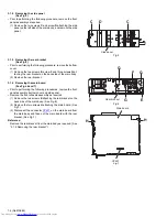
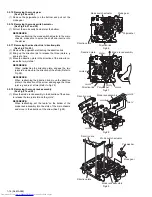
3.2.13 Removing the gear base arm / gear base link assembly
(See Fig.23 to 25)
(1) Move the gear base arm in the direction of the arrow.
(2) Insert a slotted screwdriver to the gear base spring under
the gear base arm, and release the gear base arm upward
from the boss on the gear base assembly.
(3) Remove the gear base arm from the main chassis while re-
leasing the two joints
s
.
(4) Move the gear base link assemby in the direction of the ar-
row to release the two joints
t
.
REFERENCE:
When reattaching the gear base arm, make sure that the
boss on the gear base assembly is inside the gear base
spring.
3.2.14 Removing the FFC pad
(See Fig.25 and 27)
(1) Push each joint hook
u
of the FFC pad and remove toward
the bottom.
Fig.23
Fig.24
Fig.25
Gear base
link assembly
Gear base arm
FFC pad
Joint t
Joint t
Joints s
Hook u
Hook u
Gear base arm
Screwdriver
Gear base spring
FFC pad
Gear base link
assembly
Gear base arm
Summary of Contents for KS-T707
Page 25: ... No MA069 1 25 ...
Page 44: ...3 8 Grease point 2 2 11 12 7 21 24 27 28 46 44 41 62 33 35 13 10 42 39 ...
Page 49: ...3 13 MEMO ...

