1-22 (No.MA111)
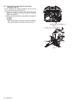
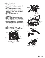
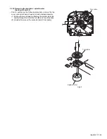
3.2.17 Removing the gears
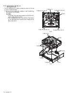
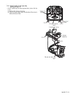
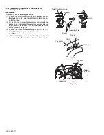
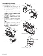
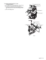
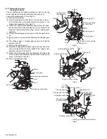
(See Figs.37 to 40)
• Prior to performing the following procedure, remove the top
cover, chassis unit, top plate assembly and pickup unit.
• Pull out the loading gear 3. (See Fig.35.)
(1) Pull out the feed gear.
(2) Move the loading plate assembly in the direction of the ar-
row to release the L side plate from the two slots m' of the
chassis rivet assembly. (See Fig.37.)
(3) Detach the loading plate assembly upward from the chas-
sis rivet assembly while releasing the joint
n'
. Remove the
slide hook and loading plate spring from the loading plate
assembly.
(4) Pull out the loading gear 2 and remove the change lock le-
ver.
(5) Remove the E ring and washer attaching the changer gear
2.
(6) The changer gear 2, change gear spring and adjusting
washer come off.
(7) Remove the loading gear 1.
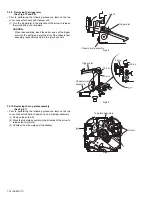
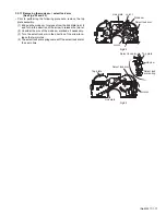
(8) Move the change plate rivet assembly in the direction of the
arrow to release from the three shafts of the chassis rivet
assembly upward. (See Fig.38.)
(9) Detach the loading gear plate rivet assembly from the shaft
of the chassis rivet assembly upward while releasing the
joint p'. (See Figs.38 and 40.)
(10) Pull out the loading gear 4.
Fig.37
Fig.38
Fig.39
Fig.40
Slot m'
Slot m'
Joint n'
Feed gear
Loading plate assembly
L side plate
Chassis rivet assembly
Joint p'
Loading gear 4
Loading gear 2
Loading gear 1
Change gear 2
Loading gear plate
rivet assembly
E ring
Shafts
Change plate
rivet assembly
Shaft
Chassis rivet assembly
Loading plate assembly
Loading plate spring
Chassis rivet assembly
Slot m'
Slot m'
Joint n'
L side plate
Slide hook
Loading gear 2
Loading gear 4
Change gear 2
Loading gear 1
E ring
Washer
Change gear spring
Loading gear plate rivet assembly
Chassis rivet assembly
Adjusting washer
Change plate
rivet assembly
Change lock lever
Summary of Contents for KD-AR260
Page 29: ... No MA111 1 29 ...
Page 97: ...3 11 MEMO ...


