


equipment key
7
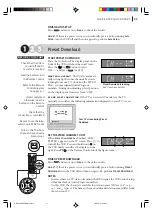
FRONT PANEL
1
STANDBY/ON
o
Button
turns VCR on/off (loading a
cassette also turns power on).
2
Cassette Loading Slot
is
where cassette is inserted;
door closes.
3
PR+/- Buttons
select a
preset position.
4
Display Panel
provides
clear view of various displays
and indicators.
5
Infrared Beam Receiving
Window
is where Remote
Control should be aimed when
in use.
6
<
Button
rewinds
the tape; initiates reverse
picture search.
7
>
Button
fast-
forwards tape; initiates
forward picture search.
8
T
Button
starts regular
recording (press once), Instant
Timer Recording (press twice);
sets duration of ITR.
9
|
Button
stops tape
temporarily during recording;
stops tape temporarily during
playback; plays back frame by
frame with each additional
press.
SAT
c
Button
enables/
disables the Auto Satellite
Programme Recording mode.
10
§
Button
stops tape;
ejects tape during Stop mode.
11
.
Button
plays back tape;
cancels Pause, Still, Slow,
Search modes.
REAR PANEL
1
Mains Power Cord
supplies power to VCR.
2
SAT CONTROL
Connector
enables connection of the
Satellite Controller for timer
recording with a satellite
receiver.
3
ANT. IN
Connector
enables
connection of aerial.
4
L-2 IN/DECODER
Connector
enables connection
of satellite receiver or second
recorder.
* DECODER function is not available in the
UK.
Diagram Key
REMOTE CONTROL
1
TV STANDBY/ON
o
Button
turns TV on/off.
2
TV/VCR Button
switches
connected TV’s mode between
TV and AV.
3
TV
Button
switches TV
input terminal.
4
START
+
/
–
Button
accesses Regular Program
screen; inputs programme
Start Time.
5
STOP
+
/
–
Button
inputs
programme Stop Time.
6
PDC Button
enables/
disables PDC recording.
*
VPS (Video Programme
System) recording is not currently
available in the U.K. and not
possible with this VCR.
7
x
Button
cancels timer-
programme.
0000 Button
resets
counter on the on-screen
display to ‘0:00:00’.
8
PROG Button
accesses
Timer Programming Set
screen.
9
C
Button
accesses
Program screens/displays to
check the programme that you
have programmed (next
programme’s information
screen appears each time
button is pressed).
10
<
Button
— same as
button on VCR.
11
T
Button
starts regular
recording (press
.
the same
time).
12
S
Button
stops tape.
13
TV PR +/– Buttons
select
the connected JVC TV's
channel.
14
r
Button
‘reviews’ timer-recorded
programme.
15
Button
accesses
Menu screen.
16
STANDBY/ON
o
Button
— same as button on VCR.
17
AUDIO Button
changes
output sound mode.
18
b
(Display) Button
switches display between
clock time and Preset
Position* (or Mode).
Preset Position (or Mode) is not
displayed during playback.
19
Number Keys
are used in
preset position selection and
the VIDEO Plus+ Timer
Programming.
20
DATE
+
/
–
Button
inputs
date of programme for timer
recording
21
DAILY Button
enables
timer recording of daily
serials.
22
WEEKLY Button
enables
timer recording of weekly
serials.
23
AUX Button
selects VCR’s
auxiliary input mode.
24
c
Button
engages timer-
standby mode.
25
Auto Tracking Button
enables/disables auto
tracking mode during
playback.
/
Button
selects tape
speed.
26
3
Button
initiates a 30-second period of
fast-motion playback.
27
.
Button
— same as
button on VCR.
28
>
Button
— same as
button on VCR.
29
|
Button
— same as
button on VCR.
30
PR
PR
Buttons
are used
for selection in on-screen
menus.
PR
+
/
–
Buttons
select a
preset position.
31
TV
+/– Buttons
control
volume of connected JVC TV.
32
D
E
Buttons
initiate
functions such as Index
Search, variable-speed search,
frame by frame playback.
33
Button
enters
selections made in on-screen
menus.
Button
— Shows
current VCR status on the TV
screen if O.S.D is set to ON.
6
AUDIO OUT (L/R)
Connectors
enable connection
of audio cassette recorder, TV
or second VCR for dubbing.
7
RF. OUT Connector
enables
connection to aerial terminal
of TV receiver.
VCR DISPLAY PANEL
1
c
Indicator
lights when
the
c
button has been
pressed to engage Timer
mode.
2
Play Indicator
lights up
during playback; blinks during
Repeat Playback or when
using Next Function Memory
for playback.
3
Record Indicator
lights up
during recording; blinks
during Instant Timer
Recording.
4
Channel Display
shows
preset position where the
station currently being
received is stored.
Mode
shows external input
mode selected (L-1 or L-2).
Clock Display
shows
current time.
Preset Position* (or Mode)
and Clock Display appear
alternately when
b
is
pressed.
*
Preset Position (or Mode) is
not displayed during playback.
5
REVIEW Indicator
blinks
after timer-recording and
shows how many programmes
have been timer-recorded.
6
SAT
c
Indicator
lights up
during Auto Satellite
Programme Recording
standby mode; blinks when
Auto Satellite Programme
Recording is in progress.
7
VCR
Indicator
lights when
the VCR is in the video mode.
At this point, the TV automati-
cally enters AV mode.
5
L-1 IN/OUT Connector
enables AV connection to TV
or second VCR.
HR-V605/606EK-EN/p02-07
1/25/03, 01:21 PM
7