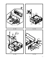
1-5
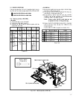
Fig. V2
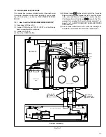
Fig. V3
<Note 4>
Spacer
Mechanism assy
(L3)
Spacer
<Note 4>
S3002
S cassette switch
<Note 4>
(L4)
Spacer
<Note 4>
5
(S3)
<Note 4>
4
(S3)
<Note 4>
WR11
Foil side
<Note 2>
6
(S8)
7
(S9)
2
8
(S3)
10
(S5)
9
(S3)
WR16 Foil side
<Note 2>
CN5322
CN703
WR15
CN2601
CN3014
WR4
Foil side
<Note 2>
WR5
Foil side
<Note 2>
WR14
Foil side
<Note 2>
CN5321
3
Fig. V4
11
(S3)
14
(S5)
13
(S5)
12
(S5)
4
Note:
When installing the Mechanism assembly, secure
the screws (S8) in the order of a , b .


