background image

EN


15

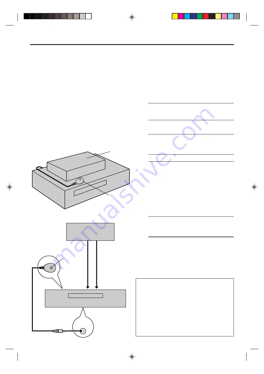
CABLE

BOX

The following procedure is required if you receive your
TV channels through a cable box (descrambler). The
Controller allows the VCR to automatically switch the
cable box channel during timer recording. The
Controller is effective for recording broadcasts that have
been programed using VCR Plus+ (

 pg. 34) or Express

timer programing (

 pg. 38).

Installing Controller

1

Situate Controller

Place the Controller so that its transmitter is
facing the cable box’s remote sensor.

Make sure the path between the Controller and

the cable box’s remote sensor is not blocked.

2

Attach Controller

Fix securely using the adhesive strip attached on
the back of the Controller.

3

Connect cable box to VCR

If your cable box does not have audio/video
output connectors

Connect the RF output terminal on the cable
box to the ANTENNA IN terminal on the rear of
your VCR.

If your cable box has audio/video output
connectors

Connect an audio/video cable between the
AUDIO/VIDEO IN connectors on the rear of
the VCR and the audio/video output connectors
on the cable box.

NOTE:

When connecting your cable box, refer to its instruction
manual.

4

Connect Controller to VCR

Connect the Controller to the CABLE BOX
Controller connector on the rear panel.

Cable Box
Control
Setting

Suggested location

Place the cable box on top of the VCR. Attach the VCR’s
Controller to the top of the VCR with the Controller’s
transmitter pointed towards the cable box’s remote
sensor.

ATTENTION:

The Controller can also control a DBS receiver. If both a cable
box and a DBS receiver are used, position the Controller so its
signal reaches the remote sensors on both the cable box and
DBS receiver.

How to control the cable box

This VCR has two separate methods to control your cable
box.

The VCR’s wireless Remote can control your cable box.
This eliminates the need for a separate cable box’s
Remote.

The VCR’s Controller can also control your cable box.
This allows the VCR to change your cable box’s channel
number during timer recording.

Each method must be set up separately. To set up the VCR’s
Remote, refer to page 69. To set up the Controller, go to
page 16.

Cable box

Cable box

Your VCR

Controller
(suggested
locations)

Transmitter

Your VCR

To

ANTENNA

IN

To
AUDIO/
VIDEO IN

To

RF output

To
Audio/video
output

or

Controller

(supplied)

 HM-DH40000U-EN15-20

1/22/3, 4:37 PM

15

Summary of Contents for HM-DH40000U

Page 1: ... TV VCR CABLE DBS POWER REMOTE CODE ABC DEF GHI JKL MNO PQRS TUV WXYZ AUX TV VOL A MONITOR DISPLAY OSD ENTER BACKK HM DH40000U D VHS DIGITAL RECORDER INSTRUCTIONS LPT0698 001A For Customer Use Enter below the Model No and Serial No which are located on the rear of cabinet Retain this information for future reference Model No Serial No MTP NTSC HM DH40000U EN01 09 1 23 3 4 59 PM 1 ...

Page 2: ...tion such as for digital video 䡲 Manufactured under license from Dolby Laboratories Dolby Pro Logic and the double D symbol are trademarks of Dolby Laboratories Confidential unpublished works Copyright 1992 1997 Dolby Laboratories All rights reserved NOTE Change or modifications not approved by the party responsible for compliance could void the user s authority to operate the equipment This equip...

Page 3: ...attention to cords at plugs convenience receptacles and the point where they exit from the product 5 Ventilation Slots and openings in the cabinet are provided for ventilation To ensure reliable operation of the product and to protect it from overheating these openings must not be blocked or covered Do not block the openings by placing the product on a bed sofa rug or other similar surface Do not ...

Page 4: ...front and rear panel the front display panel and the Remote The mark signals a reference to another page for instructions or related information Operation buttons necessary for the various procedures are clearly indicated through the use of illustrations at the beginning of each major section BEFORE YOU INSTALL YOUR NEW VCR please read the sections literature listed below CAUTIONS on page 2 IMPORT...

Page 5: ...video heads by using the optional cleaning tapes The heads get dirty in the following cases in an environment prone to extreme temperature or humidity in a dusty environment flaw dirt or mold on video tapes continuous usage for a long time Symptoms of dirty video heads The picture is not clear or does not appear There is no sound Mosaic block noise appears in the picture Black or mosaic horizontal...

Page 6: ...t Auto Tuner Set 9 Clock Setting 10 Preparations 10 Setting clock semiautomatically Semiauto Clock Set 11 Setting clock manually Manual Clock Set 12 Tuner Setting 13 Setting channels automatically Auto Channel Set 13 Setting channels manually Manual Channel Set 14 Cable Box Control Setting 15 Installing Controller 15 Setting cable box input channel brand 16 DBS Receiver Control Setting 18 Installi...

Page 7: ...ct the AC power plug to the AC outlet The clock and tuner channels will automatically be set when the antenna is connected and when the AC power cord is first connected to an AC power outlet 墌 pg 9 If Auto or channel numbers are displayed on the front display panel before the VCR is turned on the clockandtunerchannelsarebeingsetautomatically Wait until the clock time is displayed on the front disp...

Page 8: ... the component video cable between the Component video output terminals on the rear of the VCR and the component video input terminals on the TV NOTES To change the settings or set the timer program on the menu screen switch the TV s input mode for the connection with Audio cable To view the picture of 480i image format on the TV or to select and view TV broadcast connect the component video cable...

Page 9: ...nd tuner channels automatically when AC power cord is first connected to an AC outlet The antenna cable must be connected for the Plug Play setting The time and date can be set automatically by the clock setting data transmitted from one of the regular TV broadcast channels We call this TV channel the host channel and it is a PBS channel in your area 1 Perform Plug Play setup Connect the antenna c...

Page 10: ...ess fi or OK 2 Press to move the arrow to CLOCK SET then press fi or OK If CABLE BOX USERS SET CLOCK MANUALLY appears on the screen press OK to access the Clock Set screen Even if you do not press OK the Clock Set screen disappears after 5 seconds then the Clock Set screen appears automatically Turn on the VCR and the TV and select the AV mode on the TV Set the VCR TV CABLE DBS selector on the Remot...

Page 11: ...ct when Daylight Saving Time does not apply to you Press fi to move the arrow to D S T then press repeatedly until the desired setting is selected 6 Select time zone You can select the time zone automatically or manually Press fi to move the arrow to TIME ZONE press repeatedly until AUTO or the desired time zone is selected Each time you press the button the time zone changes as follows O AUTO O ATL...

Page 12: ...until the desired year appears 7 Select D S T mode Press fi to move the highlight bar to D S T then press to select ON or OFF ON Adjustment will be made by the built in clock itself OFF Select when Daylight Saving Time does not apply to you 8 Start clock Press MENU and normal screen appears To make corrections any time during the process Press fi to select the item you want to change then press VCR ...

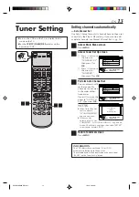
Page 13: ...ns then select RETRY to start again or select EXIT 4 Return to normal screen Press MENU INFORMATION The VCR selects the correct band TV or CATV automatically during Auto Channel Set The selected band will be displayed on the right side of BAND on the Tuner Set Up screen FUNCTION SET UP INITIAL SET UP TUNER SET UP THEN PRESS OK BAND AUTO CH SET MANUAL CH SET TV DBS SET UP SELECT WITH ARROW KEYS SEL...

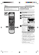
Page 14: ...els manually Manual Channel Set You can add the channels you want or delete the channels you do not want manually 1 Access Main Menu screen Press MENU 2 Access Tuner Set Up screen 1 Press to move the arrow to TUNER SET UP then press fi or OK 2 Press to move the arrow to TUNER SET then press fi or OK INITIAL SETTINGS cont VCR TV CABLE DBS 15 2 4 4 FUNCTION SET UP INITIAL SET UP TUNER SET UP THEN PRES...

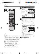
Page 15: ...When connecting your cable box refer to its instruction manual 4 Connect Controller to VCR Connect the Controller to the CABLE BOX Controller connector on the rear panel Cable Box Control Setting Suggested location Place the cable box on top of the VCR Attach the VCR s Controller to the top of the VCR with the Controller s transmitter pointed towards the cable box s remote sensor ATTENTION The Con...

Page 16: ... s output ON CH2 ON CH9 appears on the screen If your cable box is connected to your VCR s AUDIO VIDEO IN connectors on the front panel Press until ON F 1 appears on the screen If your cable box is connected to your VCR s AUDIO VIDEO IN L 1 or AUDIO VIDEO IN L 2 connectors on the rear panel Press until ON L 1 or ON L 2 appears on the screen If you do not use a cable box Press until OFF appears on ...

Page 17: ...ON CABLE BOX USERS SET CLOCK MANUALLY appears for about 5 seconds when you press OK in step 3 then the Clock Set screen appears Perform Manual Clock Set on page 12 If you press MENU after the clock has been set the Cable Box Input Channel screen in step 4 appears NOTES The Controller may not work with all types of cable box If your cable box does not respond to any code you cannot use the Controll...

Page 18: ...R If your DBS receiver has audio video output connectors Connect an audio video cable between the AUDIO VIDEO IN connectors on the rear of the VCR and the audio video output connectors on the DBS receiver NOTE When connecting your DBS receiver refer to its instruction manual 4 Connect Controller to VCR Connect the Controller to the CABLE BOX Controller connector on the rear panel DBS Receiver Cont...

Page 19: ... DBS receiver s output ON CH3 or ON CH4 appears on the screen If your DBS receiver is connected to your VCR s AUDIO VIDEO IN connectors on the front panel Press until ON F 1 appears on the screen If your DBS receiver is connected to your VCR s AUDIO VIDEO IN L 1 or AUDIO VIDEO IN L 2 connectors on the rear panel Press until ON L 1 or ON L 2 appears on the screen If you do not use a DBS receiver Pr...

Page 20: ... case make sure to leave the DBS receiver turned on and tuned to the proper channel before the scheduled start time of timer recording In addition if your DBS receiver is equipped with a timer you can also use Satellite Auto Recording 墌 pg 62 The VCR can only change the satellite channel through the Controller during timer recording If your DBS receiver cannot be operated with a Remote because it ...

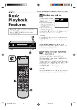
Page 21: ... CALIBRATION is set to ON default setting and PICTURE CONTROL is set to AUTO 墌 pg 54 VIDEO CALIBRATION appears on the screen and this VCR checks the tape condition during automatic tracking only cassettes recorded in the S VHS S VHS ET or VHS mode To stop playback Press STOP 7 on the Remote or STOP EJECT 7 0 on the front panel To rewind the tape when it is not running Press REW 1 To fast forward w...

Page 22: ...unter reading becomes 0 00 00 It is also reset when a tape is inserted Playing back tape repeatedly Repeat Playback You can play back a tape repeatedly 50 times While playing back a tape press and hold PLAY 3 for more than 5 seconds The play indicator on the front display panel starts flashing slowly and a tape will be played back 50 times To stop playback press STOP 7 on the Remote or STOP EJECT ...

Page 23: ...ng tracking condition Tracking Adjustments Automatic tracking adjustment This VCR automatically adjusts the tracking condition Whenever you insert a tape and start playback automatic tracking starts working and continuously analyzes the signal to enable optimum picture quality during playback Manual tracking adjustment If automatic tracking cannot eliminate noises well during playback use the manu...

Page 24: ... tape when recording is resumed from recording pause Other Useful functions for playback S VHS VHS only You can also use the following functions for playback Video Calibration 墌 pg 54 When this function is set to ON this VCR checks the condition of the tape in use during playback and recording and compensates to provide the highest possible pictures Picture Control 墌 pg 54 This function helps you ...

Page 25: ... VCR CH on the Remote to select the desired program It is impossible to select the program if the tape does not contain the multiple programs Angle Selection VIDEO 1 VIDEO 2 VIDEO 3 During normal playback press the number key 4 on the Remote to select the desired angle It is impossible to select the angle if the tape does not contain the multiple angles Sound Selection 1 STEREO 2 Dolby D During no...

Page 26: ...he hole with adhesive tape before inserting the cassette The D VHS indicator lights on the front display panel and the D VHS recording mode is selected automatically 2 Select recording channel On the front panel Press CHANNEL or On the Remote a Press TV VCR CH or or b Press the Number keys 3 Set recording speed Press REC SPEED to set the recording speed The recording speed changes each time REC SP...

Page 27: ...s REC On the Remote While holding REC press PLAY 3 If V CALIBRATION is set to ON default setting pg 54 this VCR checks the tape condition for about seven seconds then starts recording This means that the first seven seconds of the program will not be recorded If this is inconvenient for you follow the steps below 1 Press REC and PAUSE 8 to start Video Calibration 2 Then press PLAY 3 to start recor...

Page 28: ...recording length from 30 minutes to 8 hours and the VCR shuts off after recording is finished During recording press REC on the front panel repeatedly until the recording length you want appears on the front display panel The record indicator starts flashing Each time you press the button recording length increases in 30 minute intervals up to 8 hours To cancel an ITR press STOP 7 on the Remote or...

Page 29: ...ed for 5 seconds The time counter remains on the screen indicating the elapsed time The indications are not recorded 2 Exit on screen display Press OSD again NOTES The subtitles does not appear while the on screen display is displayed If the VCR is in recording pause mode 8 is always displayed The VCR status can be also displayed during playback Even if SUPERIMPOSE is set to OFF pg 57 the on scree...

Page 30: ...V Sound broadcast To record a SAP program received set 2ND AUDIO REC to ON using the menu screen NOTES When the channel is changed on the VCR The STEREO indication appears on the screen for about 5 seconds if the program is a stereo broadcast The SAP indication appears on the screen for about 5 seconds if the program is a SAP broadcast The SAP STEREO indication appears when a stereo program is acc...

Page 31: ...playback speed in SP mode 31 times in EP mode The picture may be distorted at the part where the playback speed is changed The still picture may appear during the high speed picture search of a tape recorded in D VHS format on other devices A VCR TV CABLE DBS A A PLAY 3 4 4 7 Variable Speed Picture Search S VHS VHS only You can change the speed of picture search How to use the buttons on the Remot...

Page 32: ...ible during still picture playback During still picture playback simply press CHANNEL or on the VCR or TV VCR CH or on the Remote to adjust tracking Viewing still picture frame by frame Frame by Frame Playback S VHS VHS only 1 Pause during playback Press PAUSE 8 Playback is freezed and a still picture appears 2 Advance or reverse still picture To advance a still picture press or PAUSE 8 repeatedly...

Page 33: ... During still picture playback Press and hold to start forward or 4 to start reverse slow motion playback When you release the button slow motion playback stops and a still picture appears Holding PAUSE 8 for more than 2 seconds also starts forward slow motion playback If you press PAUSE 8 again still picture resumes To resume normal playback press PLAY 3 NOTE Manual tracking is possible during sl...

Page 34: ...he clock the Main Menu screen appears after an error message is displayed Refer to page 10 for the clock setting procedure 3 Enter PlusCode number Press the appropriate Number keys to input the PlusCode number printed in the TV listings for the TV broadcast you wish to record then press OK Then If the Guide Channel Set screen appears go to step 4 If the VCR Plus Program screen appears go to step 5...

Page 35: ...ng NOTES Even if a power failure occurs the VCR keeps your timer programs However the clock time is lost if it lasts for more than 10 minutes As a result when the power is supplied again to this VCR after the power failure the following will take place 1 This VCR starts Auto Clock Set automatically to restore the clock time 2 If the clock time is restored correctly and AUTO TIMER is set to ON each...

Page 36: ... channels These guide channel numbers are also called the VCR Plus channel codes TV listings often have a section in chart form indicating the guide channel number assigned to each station For accurate VCR Plus programing the VCR Plus guide channel number for each station should match the channel number on which it is received in your area NOTES In many instances the VCR Plus guide channel numbers...

Page 37: ... channel number Press fi to move the arrow to VCR CH then press to input the number of the channel on which the guide channel s broadcasts are received Repeat steps 3 and 4 for each instance 5 Return to normal screen Press MENU FUNCTION SET UP INITIAL SET UP TUNER SET UP THEN PRESS OK CLOCK SET GUIDE CH 6 VCR CH GUIDE CHANNEL OTHER SELECT WITH ARROW KEYS SELECT OK EXIT MENU Ex When inputting the gu...

Page 38: ...Press STOP repeatedly to enter the time you want recording to stop Press and hold STOP to increase the time in 30 minute intervals 6 Set program date Press DATE The current date is displayed on the screen The date you enter appears in its place 7 Set channel number Press TV VCR CH If you are using a DBS receiver see ATTENTION FOR DBS RECEIVER USERS on next page Holding down TV VCR CH rapidly chang...

Page 39: ... VCR or through a cable box unless INPUT CH is set to OFF on Cable Set Up screen 墌 pg 16 DBS To timer record a satellite broadcast received through a DBS receiver NOTE If BAND is set to TV on the Tuner Set Up Screen 墌 pg 14 and INPUT CH is set to OFF on Cable Set Up screen 墌 pg 16 CATV will not be displayed on the Program screen If BAND is set to CATV or INPUT CH is set to ON on Cable Set Up scree...

Page 40: ...e program list To change a program press the appropriate button START STOP DATE TV VCR CH DAILY number 8 WEEKLY number 9 and or REC SPEED then press OK PROGRAM COMPLETED PRESS TIMER TO ENTER TIMER STANDBY MODE appears on the screen then press OK to return to the program list 3 Return to normal screen Press PROG CHECK 4 Reengage timer recording standby mode Press TIMER When AUTO TIMER 墌 pg 57 is se...

Page 41: ...hes to EP mode to allow complete recording This feature is especially handy when recording a broadcast of more than 2 hours in length ATTENTION If there is a conflict in the timer schedule and one program overlaps with another only the parts shown below in gray will be recorded Pattern 1 The program with the lower program number will be recorded Pattern 2 The program starting earlier will be recor...

Page 42: ...NAVI Navigation Turn on the VCR and the TV and select the AV mode on the TV Set the VCR TV CABLE DBS selector on the Remote to VCR NOTES If you press NAVI while Video Navigation is deactivated the Navigation Set Up screen appears Set NAVIGATION to ON 墌 pg 43 Video Navigation playback is possible only with the tape recorded on this VCR To record the date and time as the program title in this VCR s ...

Page 43: ...he detailed program information currently selected date channel category start time end time recording speed 6 Operational commands SYDNEY OLYMPIC 8 00 LS3 BLANK 2 00 LS3 EURO 96 ENGLAND 4 00 LS3 BLANK 1 00 LS3 Blank part BLANK appears for non recorded part the part whose information has been deleted manually 墌 pg 52 or the part where new program has been recorded Example BLANK NAVI SET UP SEARCH ...

Page 44: ... Press NAVI A VCR TV CABLE DBS B 2 3 A 2 4 C 2 3 B 4 A 1 5 C 4 BLANK NAVI SET UP SEARCH LIBRARY TITLE CATEGORY DATE TAPE NUMBER SELECT OK EXIT NAVI SELECT WITH ARROW KEYS THEN PRESS OK Navigation BLANK NAVI SET UP SEARCH LIBRARY TITLE CATEGORY DATE TAPE NUMBER SELECT OK EXIT NAVI SELECT WITH ARROW KEYS THEN PRESS OK Navigation Turn on the VCR and the TV and select the AV mode on the TV Set the VCR...

Page 45: ...The cassette mark is displayed on the left of the tape title The items without the cassette marks are the program titles included in the tape To go to another page of the lists press or To play back the desired program refer to To play back a selected program on the list screen on page 44 4 Return to normal screen Press NAVI C BLANK NAVI SET UP SEARCH LIBRARY TITLE CATEGORY DATE TAPE NUMBER SELECT...

Page 46: ... cassette marks are the program titles included in the tape To go to another page of the lists press or To play back the desired program refer to To play back a selected program on the list screen on page 44 4 Return to normal screen Press NAVI BLANK NAVI SET UP SEARCH LIBRARY TITLE CATEGORY DATE TAPE NUMBER SELECT OK EXIT NAVI SELECT WITH ARROW KEYS THEN PRESS OK Navigation BLANK NAVI SET UP SEAR...

Page 47: ...T BLANK TIME 2 00 NAVI SELECT WITH ARROW KEYS THEN PRESS OK TO LIST Navigation 4 Select tape number Press fi then press OK To go to another page of the lists press or 5 Load a cassette Insert the cassette whose number you have found in step 4 6 Select blank Press to move the arrow to STOP then press OK The VCR will start search for the beginning of the blank part then stop 7 Prepare for recording S...

Page 48: ... select the tape number for which you want to edit the title then press OK is displayed beside the tape number of the loaded cassette The cassette mark is displayed on the left of the tape title The items without the cassette marks are the program titles included in the tape To go to another page of the lists press or A VCR TV CABLE DBS A 6 A 1 7 Number keys CANCEL A 2 6 VIDEO NAVIGATION cont BLAN...

Page 49: ...and symbols with the number keys on the Remote Press the Number keys then press to enter each character Refer to the example below Ex Enter JVC NEWS 1 Press 5 JKL once to enter J then press 2 Press 8 TUV three times to enter V then press 3 Press 2 ABC three times to enter C then press 4 Press 0 twice to enter space then press 5 Press 6 MNO twice to enter N then press 6 Press 3 DEF twice to enter E...

Page 50: ...category Press fi to select the category you want then press OK 7 Return to normal screen Press NAVI VIDEO NAVIGATION cont BLANK NAVI SET UP SEARCH LIBRARY 1 SYDNEY OLYMPIC PLAY STOP DELETE EDIT 0107 ALL SPORTS TAPE BLANK 2 00 LS3 1 3 SELECT OK 2 FOOTBALL 3 EURO 96 ENGLAND 4 PROJECT XYZ SYDNEY OLYMPIC SHOW 12 21 02 SAT 6 30 AM 5 53 PM DBS 256CH LS3 SELECT WITH ARROW KEYS THEN PRESS OK EXIT NAVI Nav...

Page 51: ...ete tape information Press to move the highlight bar to YES then press OK 5 Return to normal screen Press NAVI D VCR TV CABLE DBS B 5 B 2 6 C 2 7 D 5 B 3 5 C 3 6 D 2 4 BLANK NAVI SET UP SEARCH LIBRARY 0016 EURO 2000 SEARCH RETURN DELETE EDIT TAPE NUMBER LIST 1 3 SELECT OK 0017 2 ENGLAND VS BRAZIL 0017 1 JAPAN VS KOREA 0017 SOCCER SOCCER SPORT 12 21 02 SAT 6 30 AM 5 53 PM DBS 256CH LS3 NAVI EXIT SE...

Page 52: ...creen Press fi to move the arrow to NAVI SET UP 3 Check memory The percentage of the used memory is displayed 4 Return to normal screen Press NAVI If memory is full you have to delete unwanted information to store more information in the VCR s memory F BLANK NAVI SET UP SEARCH LIBRARY 1 SYDNEY OLYMPIC PLAY STOP DELETE EDIT 0107 ALL SPORTS TAPE BLANK 2 00 LS3 1 3 SELECT OK 2 FOOTBALL 3 EURO 96 ENGLA...

Page 53: ... Function Settings FUNCTION SET UP VIDEO FUNCTION pg 54 AUDIO FUNCTION pg 55 IN OUT FUNCTION pg 56 ADDITIONAL pg 57 FUNCTION SET UP INITIAL SET UP TUNER SET UP THEN PRESS OK V CALIBRATION PICTURE CONTROL AUTO ON ON DIGITAL R3 VIDEO STABILIZER VIDEO FUNCTION AUDIO FUNCTION IN OUT FUNCTION ADDITIONAL SELECT WITH ARROW KEYS SELECT OK EXIT MENU OFF FUNCTION SET UP INITIAL SET UP TUNER SET UP THEN PRES...

Page 54: ... EDIT Minimizes picture degradation during editing recording and playback SOFT Reduces image coarseness when viewing overplayed tapes containing much noise SHARP Clearer sharper edged picture when viewing images with much flat same colored surfaces such as cartoons NOTES When you select EDIT SOFT or SHARP the selected mode will not change until you select again Select EDIT when you are editing tap...

Page 55: ...itstream and if you have a device equipped with Dolby Digital decoder set this function to Dolby D If not set this function to 2CH PCM STREAM will be used when playing back and receiving a audio signals in other new formats When this function is set to ON If a SAP program is received the SAP audio is recorded on both the normal and Hi Fi tracks The main audio is not recorded If a non SAP program i...

Page 56: ...for a wide TV set with 16 9 screen image size NORMAL 4 3 Select this for a TV set with 4 3 screen image size NOTES When TV OUTPUT 2 is set to WIDE 16 9 sometimes the screen image may be stretched vertically When TV OUTPUT 2 is set to NORMAL 4 3 sometimes subtitles may not be visible or the ends of the screen image may be cut off Normally select WIDE16 9 In order to let the equipment determine the ...

Page 57: ...n the VCR is turned on You do not have to press TIMER to engage or disengage the timer recording standby mode When this function is set to OFF You have to press TIMER to engage or disengage the timer recording standby mode When this function is set to ON various VCR status information on screen display appears on the screen NOTES When you use this VCR as the playback VCR for editing a tape be sure...

Page 58: ... the remote control code to A when you use this function 墌 pg 71 Connection varies depending on the type of JVC TV you have Refer to the TV s instruction manual when making this connection 䡵 S VHS MODE ON OFF You can determine which recording mode either S VHS mode or VHS mode is used for recording on D VHS and S VHS tapes When this function is set to ON you can record on D VHS and S VHS tapes wit...

Page 59: ...re you start important recordings You can play back S VHS ET recordings on most of S VHS VCRs and of VHS VCR equipped with SQPB S VHS QUASI PLAYBACK function Notice some VCRs are not compatible with this function While playing back a tape recorded with this function on some tapes noise may appear If playback picture becomes blurred or interrupted use a cleaning cassette During special effect playb...

Page 60: ... step 3 You cannot use the i LINK connection depending on the types of camcorder equipped with the DV connector In this case set LINC to OFF in step 3 VCR TV CABLE DBS 2 4 15 FUNCTION SET UP INITIAL SET UP TUNER SET UP THEN PRESS OK CLOCK SET JLIP ID LINC RESET NUMBER 1 GUIDE CHANNEL OTHER SELECT WITH ARROW KEYS AUTO SELECT OK EXIT MENU FUNCTION SET UP INITIAL SET UP TUNER SET UP THEN PRESS OK CLO...

Page 61: ... A B C A B Good connection examples A to D i LINK compatible devices The connections below do not form a loop Bad connection examples A to D i LINK compatible devices The connections below form a loop A B C D A B C A B C Device with three i LINK connectors NOTES You can connect as many as 63 devices including this VCR through an i LINK connection If you use a branched i LINK connection however the...

Page 62: ...rm Express Timer Programing pg 38 to timer record a satellite program Some DBS receivers output signals even if the power is off Satellite Auto Recording is not possible with those DBS receivers This function allows you to automatically record a satellite program which is timer programed on your DBS receiver Preparation Connect a DBS receiver to the AUDIO VIDEO IN or S VIDEO IN L 1 connectors on t...

Page 63: ...cedure below 1 Access Main Menu screen Press MENU 2 Select JLIP ID Set Up screen 1 Press to move the arrow to INITIAL SET UP then press fi or OK 2 Press to move the arrow to OTHER then press fi or OK 3 Set JLIP ID Number Press fi to move the arrow to JLIP ID Press to enter the desired ID number 4 Return to normal screen Press MENU NOTE For further details on the JLIP system or devices consult your ne...

Page 64: ...tion of non DTLA supported devices is not guaranteed To DV output This VCR for recording To DV IN connector DV cable not supplied DV camcorder for playback S400 DV IN D THEATER REGION 1 i LINK IN OUT DIGITAL OUT OPTICAL PCM DOLBY DIGITAL R Y L PB CB VIDEO PR CR S VIDEO S VIDEO AUDIO IN L 1 IN L 2 REMOTE PAUSE AV COMPULINK CABLE BOX ANTENNA ANTENNA OUT IN VHF UHF R L VIDEO AUDIO OUT IN COMPONENT VI...

Page 65: ...Recording Speed below 5 Start playback Press PLAY 3 on the connected device NOTE If the connected device is equipped with a superimpose OSD disable feature then set it to OFF before starting playback 6 Start recording On the front panel Press REC On the Remote Press REC and PLAY 3 at the same time NOTE If 108 REC BY HS MODE appears on the TV screen refer to Error Codes and Messages on page 77 Do n...

Page 66: ...DEO OUT To S video Input S video cable supplied IN F 1 A To rear panel REMOTE PAUSE AV COMPULINK connector Mini plug cable not supplied JVC camcorder only Audio cable supplied Camcorder for playback To Audio output To EDIT This VCR for recording To AUDIO Input S video cable supplied To S video output To S VIDEO Input Various connection for editing tapes The following three methods can be used for ...

Page 67: ...onnect also the video or S video cable Input Source Playback device Analog D VHS input S VHS VHS Selectable Recording Speed Recording device This VCR HS STD LS3 LS5 SP EP B Connection with the VCR Connect an audio S video cable between the playback VCR s audio S video output connectors and the recording VCR s audio S video input connectors When using this VCR as the recording VCR connect this VCR ...

Page 68: ...ave to set it again until you replace the Remote s batteries JVC and PANASONIC have two codes If the TV does not function with one code try entering the other 4 Operate TV Press one of the following buttons POWER TV VCR TV VCR CH TV Muting TV VOL and Number keys For some brands you must press ENTER after having pressed the Number keys to enter a channel number To operate the VCR set the VCR TV CAB...

Page 69: ...erate the VCR set the VCR TV CABLE DBS selector back to VCR NOTES Depending on the type of cable box some or all functions cannot be operated using this Remote It is impossible to control a cable box that does not have a remote sensor It s not possible to set the Remote for both your cable box and a DBS receiver at the same time You can only set the Remote to operate one of these units at a time C...

Page 70: ...Press one of the following buttons POWER TV VCR CH and Number keys For some brands you must press ENTER after having pressed the Number keys to enter a channel number To change the DBS receiver s channels press TV VCR CH or the Number keys To operate the VCR set the VCR TV CABLE DBS selector back to VCR NOTES Depending on the type of DBS receiver some or all functions cannot be operated using this...

Page 71: ... for more than 5 seconds The code currently set appears on the front display panel 5 Turn on VCR Press POWER on the Remote The code transmitted from the Remote blinks for a few seconds on the front display panel After the code disappears on the front display panel make sure that the VCR is turned on by pressing POWER on the Remote To control four VCRs with the same Remote You can control four JVC ...

Page 72: ... are clear 4 The picture stops or the black or mosaic noise appears when playing back a program recorded in D VHS mode 5 The Hi Fi sound cannot be heard 6 The D VHS indicator does not light up when playing back a D VHS cassette 7 The mosaic noise appears when receiving the scenes with fast action or switching the display POSSIBLE CAUSE The TV receiver is set to the wrong mode Automatic tracking is...

Page 73: ... intact or with the hole covered with adhesive tape Remove the cassette and cover its hole with adhesive tape or replace it with a cassette on which the safety tab is intact The program may not have been recorded in its entirety Next time be sure you have enough time on the tape to record the entire broadcast Check the programed data and set again if necessary then press TIMER again Connect the Co...

Page 74: ...ecording 8 Timer recording begins as scheduled but the channel is always incorrect 9 You moved and now VCR Plus system does not work properly 10 PROGRAM FULL is displayed on the screen POSSIBLE CAUSE The Controller is not properly connected to the VCR The input channel selected on the DBS Receiver Set screen is incorrect The VCR is not set correctly to control the DBS receiver The DBS receiver is ...

Page 75: ...pg 51 52 Set NAVIGATION to ON pg 43 For details on the recording time for Video Navigation refer to NOTES on page 42 SYMPTOM 1 Tape information screen does not appear for the currently inserted tape 2 The VCR cannot search for the desired program 3 MEMORY FULL appears on the screen when you try to start recording 4 The information data for Video Navigation is not registered POSSIBLE CAUSE The curr...

Page 76: ... to become blurred or interrupted Be sure to contact your nearest JVC dealer if such troubles occur CORRECTIVE ACTION If you need the skipped channels restore them 墌 pg 14 Press PAUSE 8 to pause the recording change channels then press PLAY 3 to resume recording Reset the correct brand codes 墌 pg 68 70 Select a different host channel during Semiauto Clock Set 墌 pg 11 or perform Manual Clock Set 墌 ...

Page 77: ...g from a camcorder connected to this VCR with the i LINK cable the image or sound may be distorted If this occurs insert a D VHS cassette in the VCR and turn off and on the VCR then start recording again If the problem is not fixed record using the audio video input connectors instead of i LINK connector Recording from camcorders and other devices via i LINK connector You may see a mosaic block no...

Page 78: ...s VCR is intended only for D VHS recording This VCR does not convert a digital signal into an analog signal for recording Switch to the analog input for recording An attempt was made to make an S VHS VHS recording using the timer function with i LINK selected on the digital tuner side The i LINK connector on this VCR is intended only for D VHS recording This VCR does not convert a digital signal i...

Page 79: ...an the VCR indefinitely remain in still mode A No It stops automatically after 5 minutes to protect the heads Q During picture search still picture playback and frame by frame playback the picture is intermittent What s the cause A Picture loss occurs when these types of playback are attempted with a tape recorded in LP mode Pressing PLAY 3 to return to normal playback will restore the picture Q W...

Page 80: ...fers outstanding high fidelity recording and playback Recording from audio input alone is not supported Dolby Digital A form of digital audio coding developed by Dolby Laboratories to deliver surround sound with 5 1 channels front left and right center rear left and right and a channel for LFE low frequency effects When you play back a digital tape encoded in Dolby Digital format the Dolby Digital...

Page 81: ...rand Remote Controlling four JVC VCRs 71 Setting Cable Box brand 69 Setting DBS receiver brand 70 Setting TV brand 68 N Next Function Memory 24 O On screen display 29 85 OPTICAL OUT 55 P PBS channel 9 PICTURE CONTROL 54 Playback 21 Plug Play 9 POWER SAVE 57 R REAR AUX L 1 56 REAR AUX L 2 56 Recording D VHS Recording 26 S VHS VHS Recording 27 Recording speed 26 27 65 Repeat playback 22 S Satellite ...

Page 82: ...loading slot 5 Remote sensor 6 STOP EJECT 7 0 button pg 21 27 7 Front display panel pg 84 MENU S VIDEO VIDEO MONO L AUDIO R TIMER CHANNEL REC PAUSE REW FF D VHS IN F 1 STOP EJECT PLAY 1 23 4 6 5 7 8 9 0 8 PLAY 3 button pg 21 9 CHANNEL and buttons pg 23 26 27 0 REC button pg 26 27 PAUSE 8 button pg 27 32 REW 1 button pg 21 31 FF button pg 21 31 D VHS button pg 27 HM DH40000U EN72 91 1 22 3 5 44 PM ...

Page 83: ... Link standard S400 DV IN D THEATER REGION 1 i LINK IN OUT DIGITAL OUT OPTICAL PCM DOLBY DIGITAL R Y L PB CB VIDEO PR CR S VIDEO S VIDEO AUDIO IN L 1 IN L 2 REMOTE PAUSE AV COMPULINK CABLE BOX ANTENNA ANTENNA OUT IN VHF UHF R L VIDEO AUDIO OUT IN COMPONENT VIDEO OUT 0 9 7 8 2 4 5 6 3 1 7 CABLE BOX Controller connector 墌 pg 15 18 8 REMOTE PAUSE AV COMPULINK terminal REMOTE PAUSE terminal 墌 pg 67 AV...

Page 84: ...and I 1 etc Clock time pg 28 2 Timer mode indicator pg 35 39 3 Record mode indicator pg 26 28 4 Play mode indicator pg 21 22 INDEX cont 5 D Theater indicator pg 25 6 D VHS indicator pg 26 27 7 S VHS indicator pg 58 59 6 7 2 3 4 5 1 HM DH40000U EN72 91 1 22 3 5 44 PM 84 ...

Page 85: ... and SAP broadcast Dolby D When playing back and receiving a Dolby Digital signals D VHS D VHS JVC DH40000 OFF CC1 CC2 CC3 CC4 B E D VHS STD 12 59 AM INDEX 9 CH 123 HD L R SAP STREAM When playing back and receiving a audio signals in other new formats PCM When playing back and receiving a PCM audio signals AUDIO 1 AUDIO 2 1 2 MIX Depends on the DV AUDIO REC setting 墌 pg 55 Icons 墌 pg 25 appears wh...

Page 86: ...ote with the polarity ª and matched correctly as indicated on the battery compartment or on the lid The Remote can operate most of your VCR s functions as well as basic functions of TV sets cable boxes and DBS receivers Point the Remote toward the remote sensor on the target component The maximum operating distance of the remote control is about 8 m NOTES If the Remote does not work properly remov...

Page 87: ... mode 14 1 Mbps STD mode 4 7 Mbps LS3 mode 2 8 Mbps LS5 mode Interface IEEE1394 compliant DTCP digital copy protection compatible VIDEO AUDIO S VHS VHS Format S VHS VHS NTSC standard Signal system NTSC type color signal and EIA monochrome signal 525 lines 60 fields Recording Playback system DA 4 Double Azimuth head helical scan system Signal to noise ratio 45 dB Frequency range Normal audio 70 Hz ...

Page 88: ...s for your JVC product you may contact your local JVC Dealer From the 48 Continental United States call toll free 1 800 882 2345 or on the web at www JVC com Dear customer In order to receive the most satisfaction from your purchase please read the instruction booklet before operating the unit In the event that repair is necessary or for the address nearest your location within the Continental Uni...

Page 89: ...rovided with the products or if the model or serial number has been altered tampered with defaced or removed 2 Initial installation and installation and removal for repair 3 Operational adjustments covered in the Owner s Manual normal maintenance video and audio head cleaning 4 Damage that occurs in shipment due to act of God and cosmetic damage 5 Signal reception problems and failures due to line...

Page 90: ...90 EN MEMO HM DH40000U EN72 91 1 22 3 5 44 PM 90 ...

Page 91: ...EN 91 HM DH40000U EN72 91 1 22 3 5 44 PM 91 ...

Page 92: ...STD 1394A 2000 1394 INTERFACE IMPLEMENTATION GUIDELINE FOR D VHS VERSION 1 00 AND DTCP DIGITAL TRANSMISSION CONTENT PROTECTION SPECIFICATION VERSION 1 1 THE SPECIFICATIONS USE OF THIS PRODUCT WITH ANOTHER PRODUCT DEVICE COMPONENT PART OR MATERIAL THAT IS NOT IN CONFORMITY OR COMPLIANT WITH THE SPECIFICATIONS OR THAT IMPLEMENT THE SPECIFICATIONS IN A NON CONFORMING OR NON COMPATIBLE MANNER WITH THI...

Reviews: