(No.YA385)1-41
< Page 2 of screen >
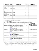
5.1.7 DISPLAY METHOD WHEN RASTER IS NOT AVAILABLE
In a state where a display screen does not appear due to the failure of this unit, the POWER LED (blue) and LAMP LED (orange) can
light up and display a trouble mode.
The factors in case the power is forcibly shut down at the time of failure are memorized and those are displayed.
EXPLANATION ON ACTION
If NG is detected on an item being diagnosed, turn off the power on this unit. As soon as the power goes off, turn on and off POWER
LED and LAMP LED immediately. After the power is shut down, it becomes impossible to turn on the power until the power cable
is either plugged in or unplugged from the AC outlet.
• When [1] and [3] take place at the same time, give priority to [1], and [2] will not take place simultaneously with [1] and [3].
Detection item
Display
Detection content
Diagnosis
signal (line)
Detection timing
Fan lock
FAN
Not used.
---
---
Abnormal of operation of
PANEL
ALM
Not used.
---
---
Abnormal rise
oftemperature in PANEL
TMP
Not used.
---
---
Abnormal rise of
temperature in AUDIO
PWB
ATP
Not used.
---
---
Short circuit detection of
AUDIO PWB
ASH
Not used.
---
---
Panel communication
PNL
Not used.
---
---
Sub memory
MEM
Not used.
---
---
Temp. sensor
TMP
Not used.
---
---
Audio control
AIO
Not used.
---
---
Card viewer
ESS
Not used.
---
---
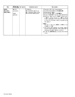
Check item
Contents
Classifications
LED flash cycle
POWER LED
LAMP LED
Lamp does not light up Detection of lamp return (LAMP_RTN) signals output
depending on the status of the lamp supply electric
current monitored constantly within the lamp ballast unit.
(H = Off)
CN311
[MAIN DRIVE PWB]
3
0.1 sec interval Simultaneously
Lamp goes out
Detection of lamp return (LAMP_RTN) signals output
depending on the status of the lamp supply electric
current monitored constantly within the lamp ballast unit.
(H = Off)
CN311
[MAIN DRIVE PWB]
3
0.1 sec interval Simultaneously
Lamp cover open
Detection of the interlock switch status for the lamp
cover. (H = Abnormal)
S0201
[LAMP COVER SW PWB]
3
0.1 sec interval Simultaneously
Abnormal DD CPU
circuit
Detection of serial communication error between MAIN
DRIVE PWB and RECEIVER PWB.
IC3701
[MAIN DRIVE PWB]
2
----------
0.5 sec interval
Fan lock (stop)
Detection of LOCK signals outputting the operation
(circuit) status of the cooling fan. (H=Abnormal)
IC8005
[FAN CONTROL PWB]
1
0.5 sec interval Alternately
Abnormal D-ILA
DEVICE temperature
Detection of abnormal inner cabinet temperature. (53
°
C)
IC2001
[TEMP. SENSOR PWB]
1
0.5 sec interval Alternately


